


WARNING: Beforeinspecting, cleaningor servicing the machine,shut off engine,wait for all
moving partsto come to a complete stop, disconnect spark plug wireand move wire awayfrom
spark plug. Failureto follow these instructions canresult in serious personalinjury or property
damage.
4. Thegear oil level iscorrect if thegear oil
isapproximately halfway upthe sideofthe
main driveshaft.
5. Ifthe gearoil levelislow, addgear oil as
described next.If the gearoil levelisokay,
securely replacethe oil fill plug.
IMPORTANT:Donot operatethe tiller ifthe
gear oil level is low. Doingso will result in
severedamageto the transmission com-
ponents.
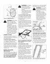
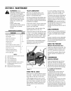
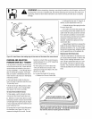
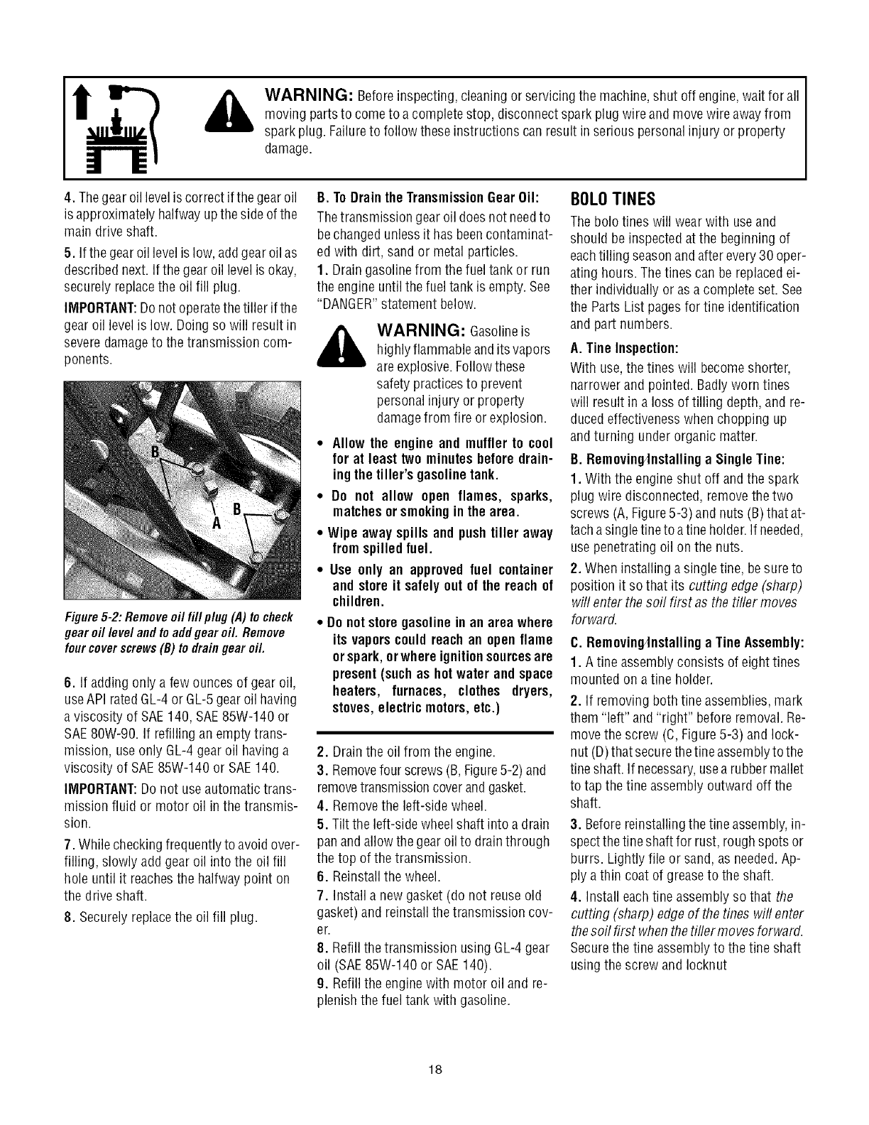
Figure5-2: Removeoil fill p/ug (,4)to check
gear oil level and toaddgear oil. Remove
fourcoverscrews(B) to draingear oil.
6. If adding only a few ounces of gear oil,
useAPIrated GL-4or GL-5gearoil having
a viscosity of SAE140, SAE85W-140 or
SAE80W-90. If refilling an emptytrans-
mission, useonly GL-4gear oil having a
viscosity of SAE85W-140 or SAE140.
IMPORTANT:Do not useautomatic trans-
mission fluid or motor oil inthe transmis-
sion.
7. Whilecheckingfrequently to avoidover-
filling, slowly add gear oil into the oil fill
hole until it reachesthe halfwaypoint on
the driveshaft.
8. Securely replacethe oil fill plug.
B. ToDrain theTransmissionGearOil:
Thetransmission gear oil does notneedto
bechanged unless it hasbeencontaminat-
ed with dirt, sand or metal particles.
1. Draingasolinefrom thefuel tank or run
the engine until thefuel tank is empty.See
"DANGER"statement below.
WARNING: Gasolineis
highlyflammableandits vapors
areexplosive. Followthese
safety practicesto prevent
personalinjury or property
damagefrom fire or explosion.
Allow the engine and muffler to cool
for at least two minutesbeforedrain-
ingtheUller's gasolinetank.
Do not allow open flames, sparks,
matchesorsmokingin thearea.
Wipe away spills and pushtiller away
fromspilled fuel.
Use only an approvedfuel container
and store it safelyout of the reach of
children.
Do notstoregasoline in an area where
its vaporscould reach an openflame
orspark, orwhere ignitionsourcesare
present(suchas hot water and space
heaters, furnaces, clothes dryers,
stoves,electric motors,etc.)
2. Drainthe oil from the engine.
3. Removefour screws (B,Figure5-2)and
removetransmissioncoverandgasket.
4. Removethe left-side wheel.
5. Tilt the left-side wheelshaft into a drain
panand allowthe gearoil to drainthrough
the top of thetransmission.
6. Reinstallthe wheel.
7. Install a newgasket (do not reuseold
gasket)and reinstall the transmission cov-
er.
8. Refill the transmission using GL-4gear
oil (SAE85W-140 or SAE140).
9. Refill the enginewith motor oil and re-
plenishthe fuel tank with gasoline.
BOLOTINES
Thebolo tines will wear with useand
should be inspectedatthe beginning of
eachtilling seasonand after every30 oper-
ating hours. Thetines can be replacedei-
ther individually or as a completeset. See
the Parts List pagesfor tine identification
and part numbers.
A. Tine Inspection:
With use,the tines will becomeshorter,
narrower and pointed. Badlyworn tines
will result in a loss of tilling depth, and re-
ducedeffectivenesswhen chopping up
andturning under organic matter.
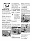
B. Removin_nstalling a Single Tine:
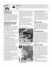
1. With the engine shut off andthe spark
plug wire disconnected,remove thetwo
screws (A,Figure5-3)and nuts (B)that at-
tachasingletineto atine holder. If needed,
usepenetrating oil on the nuts.
2. When installing a singletine, besureto
position it so that its cutting edge (sharp)
will enter thesoil first asthe tiller moves
forward.
C. Removin_nstalling a TineAssembly:
1. Atine assemblyconsists of eighttines
mounted on atine holder.
2. If removing both tine assemblies,mark
them "left" and "right" beforeremoval. Re-
move the screw (C, Figure5-3) and lock-
nut (D)that securethetine assemblyto the
tineshaft. If necessary,usea rubber mallet
to tapthe tine assembly outward off the
shaft.
3. Beforereinstallingthetine assembly,in-
spectthe tineshaft for rust, roughspots or
burrs. Lightly file or sand, as needed.Ap-
ply a thin coat of greaseto the shaft.
4. Install eachtine assemblyso that the
cutting (sharp) edge of thetines wifl enter
thesoil first whenthetiflermovesforward.
Securethe tine assemblyto the tine shaft
usingthe screwand Iocknut
18