


6
3
Section
D
A
N
G
E
R
KEEP HANDS and FEET AWAY
W
A
R
N
IN
G
T
H
R
O
W
N
O
B
J
E
C
T
H
A
Z
A
R
D
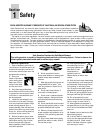
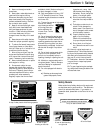
Objects such as rocks, pebbles and
small debris will be thrown violently by
the cutting head, resulting in significant
hazard to eyes and exposed body parts!
Keep children, pets and bystanders 50
feet away from machine while operating.
Be alert to hidden obstacles.
R
O
T
A
T
I
N
G
C
U
T
T
I
N
G
H
E
A
D
Do not service or adjust cutting head or
other moving parts unless engine is stopped
and spark plug wire is disconnected.
1904403 (1/97)
•
•
•
3x
D
A
NG
ER
KEEP HANDS and FEET AWAY
W
A
R
N
IN
G
T
H
R
O
W
N
O
B
J
E
C
T
H
A
Z
A
R
D
O
b
j
e
c
t
s
s
u
c
h
a
s
r
o
c
k
s
,
p
e
b
b
l
e
s
a
n
d
s
m
a
l
l
d
e
b
r
i
s
w
i
l
l
b
e
t
h
r
o
w
n
v
i
o
l
e
n
t
l
y
b
y
t
h
e
c
u
t
t
i
n
g
h
e
a
d
,
r
e
s
u
l
t
i
n
g
i
n
s
i
g
n
i
f
i
c
a
n
t
h
a
z
a
r
d
t
o
e
y
e
s
a
n
d
e
x
p
o
s
e
d
b
o
d
y
p
a
r
t
s
!
K
e
e
p
c
h
i
l
d
r
e
n
,
p
e
t
s
a
n
d
b
y
s
t
a
n
d
e
r
s
5
0
f
e
e
t
a
w
a
y
f
r
o
m
m
a
c
h
i
n
e
w
h
i
l
e
o
p
e
r
a
t
i
n
g
.
B
e
a
l
e
r
t
t
o
h
i
d
d
e
n
o
b
s
t
a
c
l
e
s
.
R
O
T
A
T
I
N
G
C
U
T
T
I
N
G
H
E
A
D
D
o
n
o
t
s
e
r
v
i
c
e
o
r
a
d
j
u
s
t
c
u
t
t
i
n
g
h
e
a
d
o
r
o
t
h
e
r
m
o
v
i
n
g
p
a
r
t
s
u
n
l
e
s
s
e
n
g
i
n
e
i
s
s
t
o
p
p
e
d
a
n
d
s
p
a
r
k
p
l
u
g
w
i
r
e
i
s
d
i
s
c
o
n
n
e
c
t
e
d
.
1904
4
03 (1/
9
7
)
•
•
•
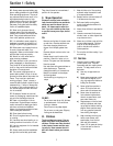
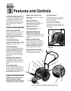
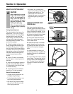
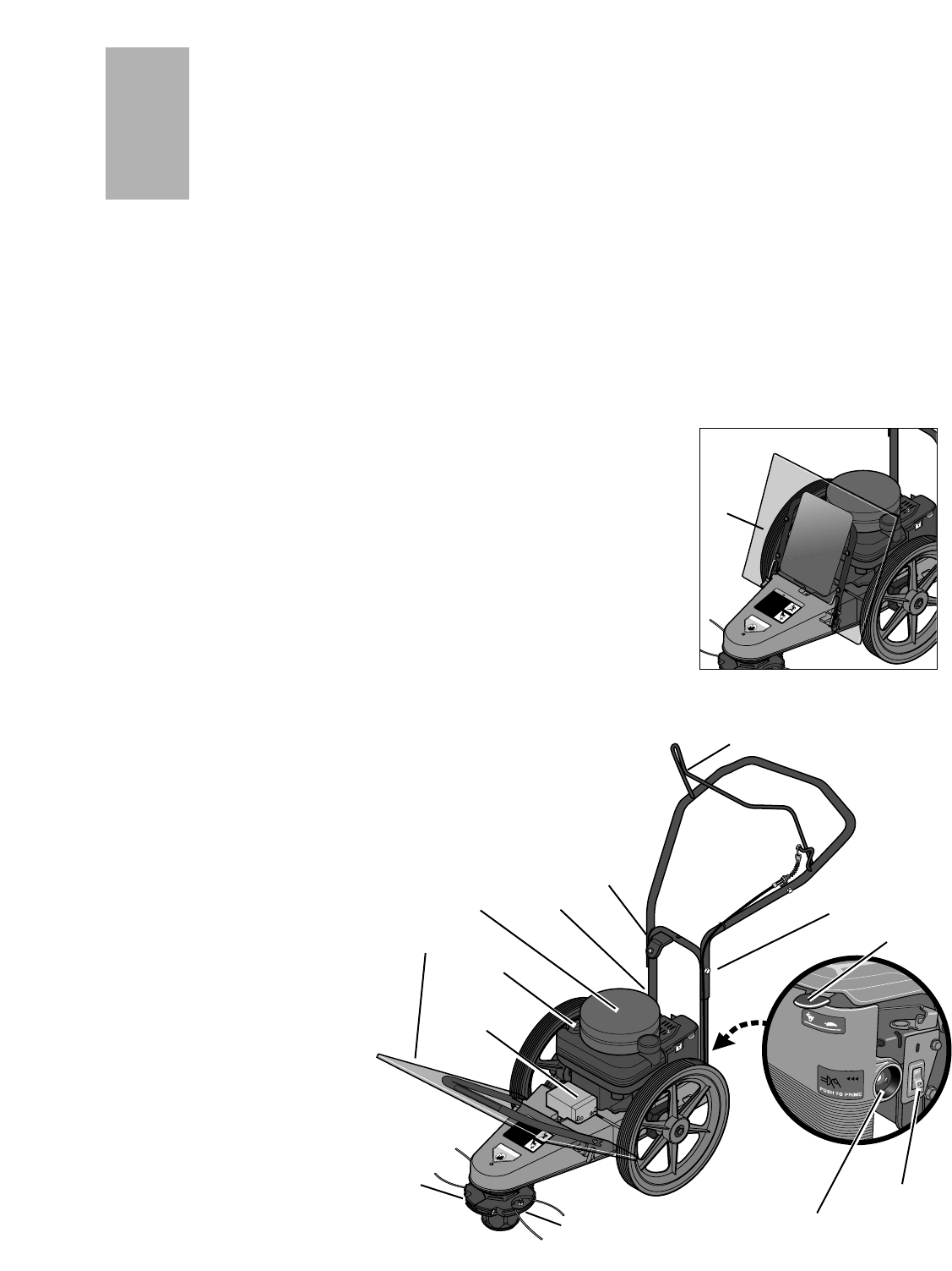
Figure 3-1: Features and controls (electric start model shown)
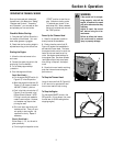
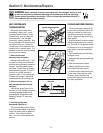
Figure 3-1A: Debris shield in operat-
ing position.
E
Features and Controls
Engine Throttle Control Lever
Use this lever (F, Fig. 3-1) to regulate
engine speed.
Engine On/Off Switch
Put switch (G, Fig. 3-1) in ON
position before starting engine. Use
OFF position to stop engine.
Engine Recoil Starter
The recoil starter (H, Fig. 3-1) is
mounted on the engine.
Engine Ignition Keyswitch
(electric start model only)
The engine ignition keyswitch (I, Fig. 3-
1) allows starting the engine from the
handlebar.
Engine Foam Debris Filter
The foam debris filter (J, Figure 3-1)
protects the engine from accumula-
tions of cut materials that can clog the
engine cooling passages. See the
Maintenance Section for information
on servicing this important filter.
Battery (electric start model)
The battery (K, Fig. 3-1) starts the en-
gine via the ignition keyswitch.
The following are features and controls
found on the various models of the
Trimmer/Mower. Read the description
and location of each feature and con-
trol. Unless otherwise noted, a de-
tailed descriptions of each feature and
control can be found in “Section 4:
Operation.”
MOWER CONTROLS/FEATURES
Trimmer Head Control Bail
The control bail (A, Fig. 3-1) is used to
start and stop trimmer head motion.
Pull the control bail up against the
handlebar to activate the trimmer
head. Let go of the control bail to stop
the trimmer head.
Cutting Height Settings
The trimming head (B, Fig. 3-1) is ad-
justable to an infinite number of height
settings from 1-1/2"-to-4-1/2".
Line Mounting Plates
The two cutting lines are secured with
bolted clamp plates (C, Fig. 3-1). For
most jobs, line length should be ad-
justed equally. For some jobs, the
overall line swath can be increased
from the normal 22" to 25" by offset-
ting the line.
Handlebar Height Adjustment
The handlebar (D, Fig. 3-1) has two
height settings (requires removal and
reinstallation of two screws and lock-
nuts).
Plastic Debris Shield
A heavy-duty plastic shield (E, Fig. 3-1
and 3-1A) protects the engine from all
manner of debris. The shield tilts for-
ward for access to oil, fuel fill, and bat-
tery (electric start units) areas.
ENGINE CONTROLS/FEATURES
IMPORTANT: Refer to the separate
engine manufacturer’s Engine
Owner’s Manual for detailed informa-
tion about the controls on the engine.
Fuel Primer Button
The fuel primer button (L, Figure 3-1)
allows a cold engine to be primed for
faster, easier starting.
Engine Oil Fill/Oil Dipstick
The engine oil fill hole/oil dipstick (M,
Figure 3-1) is located on the right side
of the engine.
A
C
B
J
K
L
M
D
E
F
G
H
I