


12
ADJUSTING TRIMMER
HEAD ENGAGEMENT
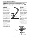
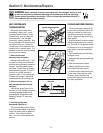
A. To test for correct belt tension, en-
gage the control bail while the engine is
running. If correct, the trimmer head
will rotate when the control bail is
pulled back fully against the handlebar.
B. If belt tension is too loose, the trim-
mer head will move slowly or not at all
and squealing from belt slippage may
be heard when the bail is engaged.
C. If belt tension is too tight, the trim-
mer head will rotate before the control
bail is moved or when there is no free
play in the bail.
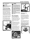
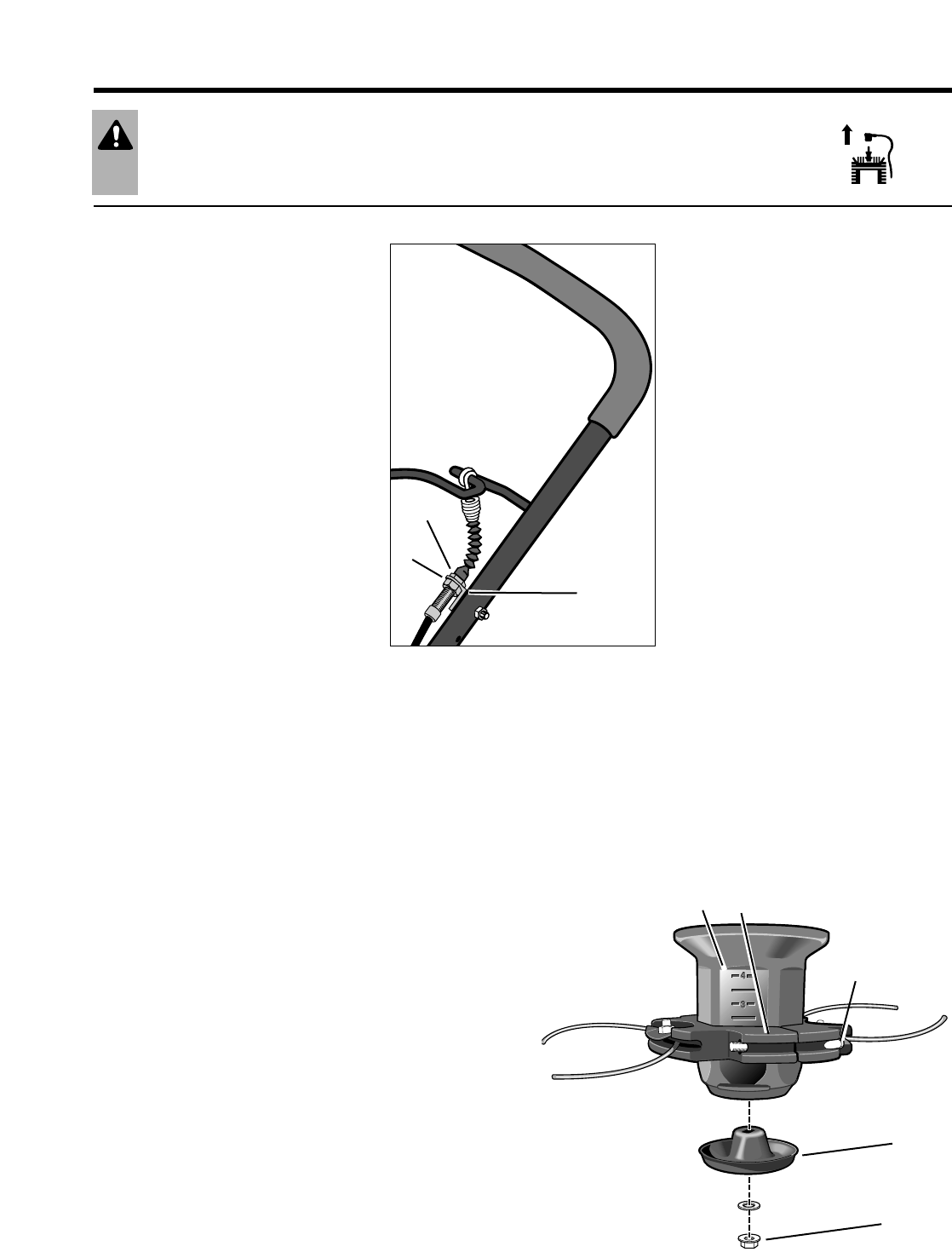
D. To make an adjustment to belt ten-
sion, shut off the engine, let all moving
parts stop completely, and adjust the
position of the two nuts on the stud
shown in Figure 5-2 as described next:
1. To tighten belt tension, close the
bail, move the upper nut (A, Figure
5-2) upward, then move the lower
nut (B) upward. To loosen belt ten-
sion, move the lower nut down and
then the upper nut down. Tighten
both nuts securely.
2. If adjustments over time move the
nuts to the top of the threaded stud,
the cable bracket (C) can be moved
down the handlebar to the next hole.
This permits a new range of adjust-
ments.
REMOVING & REPLACING THE
TRIMMER HEAD
A. Stop the engine and wait for all
moving parts to stop. Disconnect
spark plug wire and move it away from
the spark plug. Remove the ignition
key on electric start models.
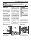
B. Two bolts (A, Figure 5-3) secure the
trimmer head (B) to the spindle head
(C). Loosen both bolts (not the nuts)
sufficiently to open up the trimmer
head enough to let it slide down the
spindle head and past the two stops.
Do not attempt to remove the bolts
completely— they are permanently at-
tached.
Install the new trimmer head in the
same way the old unit was attached.
Open it enough to slide it on the spin-
dle head. Tighten the hardware se-
curely (to 75 in/lbs.).
C. If the wear cup (D, Figure 5-3) is
also worn, replace it. To do so, insert a
phillips head screwdriver in the hole at
the top-front of the deck while remov-
ing nut (E). Discard the old cup, posi-
tion the new wear cup, and replace nut
(E) securely.
Section 5: Maintenance/Repairs
Figure 5-2: Belt tension adjustment.
B
C
A
WARNING Before inspecting, cleaning or servicing the unit, shut off engine, wait for all parts
to come to a complete stop, disconnect spark plug wire and move wire away from spark plug.
Remove ignition key on electric start models. Failure to follow these instructions can result in
serious personal injury or property damage.
A
B
E
C
D
Figure 5-3