


Assembly
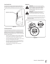
Handle
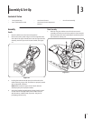
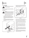
Place the shift lever in the Forward-6 position1.
Remove the lower plastic wing nut and carriage bolt from 2.
each side of the upper handle; then raise the upper handle
assembly until it snaps over the lower handle. See Figure
3-1.
Looking beneath the handle panel, check that all of the 3.
cables (steering, auger, shift, and drive) are properly routed
and not pinched or kinked.
NOTE: Make certain the upper ends of each cable are
seated properly in the proper brackets.
Secure the handle by tightening the plastic knob located 4.
on both the left and right sides of the handle. Remove
and discard any rubber bands, if present. They are for
packaging purposes only.
Contents of Carton
Two Ignition Keys• One Snow Thrower• One Chute Assembly•
One 110V Extension Cord• One Snow Thrower Operator’s •
Manual
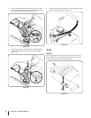
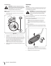
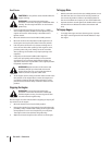
Chute Assembly
Remove wing nut and hex screw from chute control 1.
assembly and clevis pin and cotter pin from chute support
bracket. Position the chute assembly (forward-facing) over
the chute base. See Fig. 3-2.
Figure 3-1
1
1
2
Figure 3-2
Assembly & Set-Up
3
7