


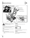
Auger Control
WARNING! Prior to operating your snow thrower,
carefully read and follow all the instructions below.
Perform all adjustments to verify your snow thrower
is operating safely and properly.
Check the adjustment of the auger control as follows:
When the auger control is released and in the disengaged 1.
“up” position, the cable should have very little slack. It
should NOT be tight.
In a well-ventilated area, start the snow thrower engine. 2.
Refer to Starting the Engine on page 15. Make sure the
throttle is set in the FAST position.
While standing in the operator’s position (behind the snow 3.
thrower), engage the auger.
Allow the auger to remain engaged for approximately ten 4.
(10) seconds before releasing the auger control. Repeat this
several times.
With the throttle control in the FAST (rabbit) position and 5.
the auger control in the disengaged “up” position, walk to
the front of the machine.
Confirm that the auger has completely stopped rotating 6.
and shows NO signs of motion.
IMPORTANT: If the auger shows ANY signs of rotating,
immediately return to the operator’s position and shut off the
engine. Wait for ALL moving parts to stop before readjusting the
auger control.
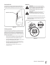
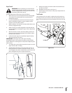
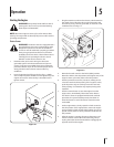
To readjust the control cable, loosen the hex jam nut on the 7.
auger control cable “Z” fitting.
Thread the ferrule without turning the cable onto the “Z” 8.
fitting until there is no slack in the cable. See Fig. 3-11. Do
not overtighten the cable. Hold the flats on the ferrule with
pliers and tighten the jam nut against the ferrule.
Rotate the coupling end of the cable counterclockwise to 9.
provide more slack.
Retighten the hex jam nut. See Fig. 3-11.10.
Repeat Auger Control Test to verify proper adjustment has 11.
been achieved.
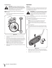
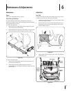
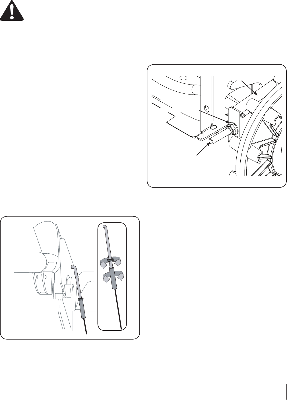
Track Tension
Over time the track can stretch. To adjust the track tension turn
the flange lock nut on the front of the track side plate. This pulls
the “J” bolts attached to the axle and tightens the tracks. See Fig.
3-12.
Figure 3-11
“J” Bolt
Flange Lock Nut
Track Side Plate
Figure 3-12
11se c t i O n 2 — as s e M b l y & se t -up