


11
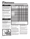
ENGINE MAINTENANCE
• Maintain the correct engine oil level and
change the oil as recommended (more
often in dusty conditions).
• Keep the air filter clean. Operating the
engine with a dirty, clogged air filter can
cause poor performance and damage to
the engine. Never operate engine
without air filter installed.
• Keep the spark plug clean and properly
gapped. Replace every 2 years.
• The engine cooling fins must be kept
clean to prevent overheating of the
engine.
• If the engine is equipped with a spark
arrester, clean it every year.
• Clean, check or adjust the following
items according to the instructions in
the Engine Owner’s Manual: fuel tank,
fuel filter, clutch shoes, idle speed, valve
clearance and fuel tubes.
TINE REMOVAL
AND INSTALLATION
The tines wear with use and should be re-
placed if tilling takes longer than usual or
if the soil does not mix thoroughly. In ad-
dition to the standard 10" tilling width tine
pattern, the tines can be arranged in a
narrow, 4
1
/2" tilling width pattern for
smaller areas, and a special pattern for
stony soil conditions.
Arranging Tines
for Narrow Tilling
1. Prop the machine forward so it rests
on the front of the tubular carrying
handle. The work surface should be flat
and firm.
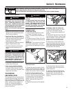
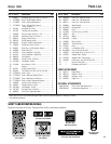
2. Flip open the ring (A, Figure 12) on the
left side ring lock pin and remove the ring
lock pin.
IMPORTANT: The ring lock pin (A, Figure
12) is under spring tension – use care
when removing or replacing the ring lock
pin.
3. Remove the outer tine section (do not
remove inner tine section) and mark it as
to which side it is from (left or right) and
whether it’s an outer or inner tine section.
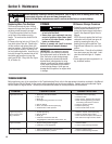
4. Slide one of the long bushings (B,
Figure 13), provided with the unit, onto
the shaft. Insert the ring lock pin through
the rounded side of the tine shaft and
snap the ring down over the shaft (see
DETAIL - Ring Lock Pin, Figure 10, in
Section 4).
5. Repeat this procedure on the opposite
side.
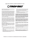
Arranging Tines for Stony Soil
1. Prop the machine forward so it rests
on the front of the tubular carrying
handle. The work surface should be flat
and firm.
2. Remove the ring lock pin (A, Figure 12)
from both sides of the unit. Remove both
outer tine sections. Be sure to mark each
section as a left or right side tine and
whether it is an inner or outer section.
3. Remove the inner tine sections and
swap their positions (the inner right-side
section goes onto the left side of the ma-
chine, and the inner left-side goes onto
the right side of the machine).
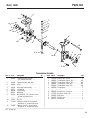
4. Reinstall the two outer tine sections
onto the sides from which they were re-
moved (Figure 14).
5. Insert the ring lock pins through the
rounded side of the tine shafts and snap
the rings down over the shafts (see
DETAIL - Ring Lock Pin, Figure 10, in
Section 4).
The temperature of the muffler and adja-
cent engine areas may exceed 150
o
F
(65
o
C). Contact may cause burns. Avoid
these areas. Remove the spark plug
lead and ground the lead to the engine to
prevent accidental starts and fires.
Failure to do this could cause personal
injury.
WARNING
Avoid contact with the cutting edges on
the tines.
To avoid personal injury when removing
or installing tines, wear heavy work
gloves. The engine must be off, all
moving parts stopped, and the spark
plug wire disconnected from the spark
plug and moved away from the plug.
WARNING
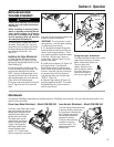
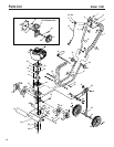
Figure 12: Standard wide tine pattern and
ring lock pin location.
A
Before inspecting, cleaning or servicing the machine, shut off engine, wait for moving parts to stop, dis-
connect spark plug wire and move wire away from spark plug.
Failure to follow these instructions can result in serious personal injury or property damage.
WARNING
Do not tamper with the engine governor
screw which is factory-set for the proper
engine speed. Overspeeding the engine
beyond the factory high speed setting
can be dangerous and will void the
engine warranty. Authorized service
shall be sought if a problem exists.
WARNING
Figure 13: Narrow tilling tine configuration.
B
Figure 14: Stony soil tine pattern.
Section 5: Maintenance