


6
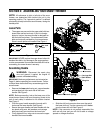
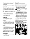
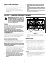
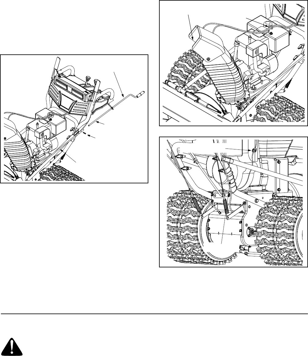
Attaching Chute Directional Control
• Remove the hairpin clip from the upper rod and
slide the upper rod through the bracket and into the
lower rod. See Figure 4.
• Align the two holes on both chute cranks and insert
the hairpin clip removed earlier, through these
holes. See Figure 4.
Figure 4
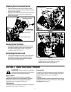
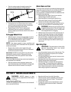
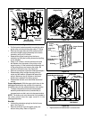
Routing Chute Tilt Cables
• If not already routed, slip the cables that run from
beneath the handle panel to the discharge chute
through the cable guide located on top of the
engine housing. See Figure 5.
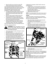
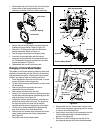
Connecting Alternator Lead
• Unwrap the headlight wire which is attached to the
headlights, beneath the handle panel. Wind the
wire around the lower right handle until excess
slack is removed. See Figure 6.
Figure 5
Figure 6
• Plug the wire from the headlight into the alternator
lead located on the right side of the engine,
beneath the fuel tank. See Figure 6.
SECTION 3: KNOW YOUR SNOW THROWER
WARNING: Read, understand, and follow
all instructions and warnings on the machine
and in this manual before operating.
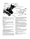
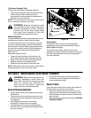
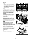
Chute Tilt Control
The distance snow is thrown can be changed by
adjusting the angle of the chute assembly. Move the
chute tilt control forward to decrease the distance,
toward the rear to increase. See Figure 7.
Throttle Control
The throttle control is located on the engine. It regulates
the speed of the engine. See Figure 7.
Discharge Chute
The angle of the discharge chute controls the distance
that the snow is thrown. Tilt the discharge chute up for
greater distance; tilt down for less distance.
Skid Shoes
The space between the shave plate and the ground can
be adjusted by positioning the skid shoes. Refer to Skid
Shoe Adjustment on page 12.
Upper Chute Crank
Lower Chute Crank
Hairpin Clip
Upper Chute
Crank Bracket
Cable Guide
Discharge Chute
Alternator Lead
Lamp Wire