


16
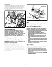
• Secure the two halves with the two bolts and lock
washers removed earlier. Refer to Figure 18.
• Attach the “Z” fitting of the cable into the brake
bracket assembly. Refer to Figure 19.
• Slip the auger control belt over engine pulley.
• Insert ferrule on auger idler rod into bracket
assembly and secure with flat washer and cotter
pin. Reassemble the large shoulder bolt and lock
washer as shown in Figure 18.
• Reassemble belt cover and chute crank.
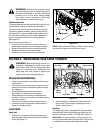
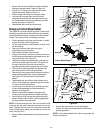
Changing Friction Wheel Rubber
The rubber on the friction wheel is subject to wear and
should be checked after the first 25 hours of operation,
and periodically thereafter. Replace the friction wheel
rubber if any signs of wear or cracking are found.
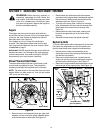
• Drain the gasoline from the snow thrower, or place
a piece of plastic under the gas cap.
• Tip the snow thrower up and forward, so that it rests
on the housing.
• Remove six screws from the frame cover
underneath the snow thrower.
• Remove the left wheel from the axle.
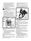
• Using a 7/8” wrench, hold the hex shaft and remove
the hex bolts and bell washer and bearing from left
side of the frame. See Figure 22.
• Holding the friction wheel assembly, slide the hex
shaft out of the left side of the unit. The spacer on
the right side of the hex shaft will fall and the
sprocket should remain hanging lose in the chain.
• Lift the friction wheel assembly out between the
axle shaft and the drive shaft assemblies.
• Remove the four screws which secures the friction
wheel rubber between the friction wheel plates.
See Figure 22. Discard the old friction wheel
rubber.
• Reassemble the new friction wheel rubber to the
friction wheel assembly, tightening the four screws
in rotation and with equal force.
• Insert the pin from the shift arm assembly into the
friction wheel assembly and hold assembly in
position. See Figure 22.
• Slide the hex shaft through the left side of the
housing and through the friction wheel assembly.
• Insert the hex shaft through the sprocket and the
spacer. Make certain that the chain engages both
the large and the small sprocket.
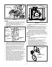
NOTE: If the sprocket fell from the snow thrower while
removing the hex shaft, place the sprocket on the hex
shaft. Position the hex hub of the sprocket toward the
friction wheel when sliding the sprocket on to the hex
shaft. See Figure 23.
• Secure with the bell washer and hex bolt removed
earlier.
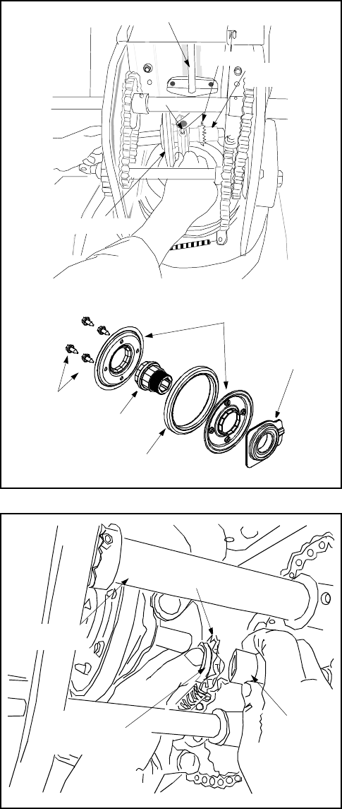
Figure 22
Figure 23
• Secure the frame cover with six self-tapping
screws. Put the snow thrower down to its normal
operating position.
NOTE: If you placed plastic film under the gas cap, be
certain to remove it.
Shift Arm
Assembly
Pin
Friction
Wheel
Sprocket
Spacer
Shift Arm Assembly
Pin
Sprocket
Spacer
Friction Wheel
Plates
Screws
Friction Wheel Rubber
Hub
Bearing
Shift Arm
Assembly
Pin
Friction
Wheel
Sprocket
Spacer
Sprocket
Hex Hub
Spacer
Of Sprocket
Hex Shaft