


14
SECTION 7: SERVICING YOUR SNOW THROWER
WARNING: Before servicing, repairing, or
inspecting, disengage all clutch levers and
stop engine. Wait until all moving parts have
come to a complete stop. Disconnect spark
plug wire and ground it against the engine to
prevent unintended starting.
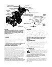
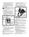
Augers
The augers are secured to the spiral shaft with two
shear bolts and hex lock nuts. If you hit a foreign object
or ice jam, the snow thrower is designed so that the
bolts may shear. See Figure 16.
If the augers do not turn, check if the bolts have
sheared. Two replacement shear bolts and hex lock
nuts have been provided with the snow thrower. Refer
to Loose Parts on page 5.
IMPORTANT:
NEVER replace the auger shear bolts with
standard hex bolts. Any damage to the auger gearbox
or other components, as a result of doing so, will NOT
be covered by your snow thrower’s warranty.
Shave Plate and Skid Shoes
The shave plate and skid shoes on the bottom of the
snow thrower are subject to wear. They should be
checked periodically and replaced when necessary.
NOTE: The skid shoes on this machine have two wear
edges. When one side wears out, they can be rotated
180° to use the other edge.
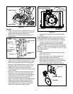
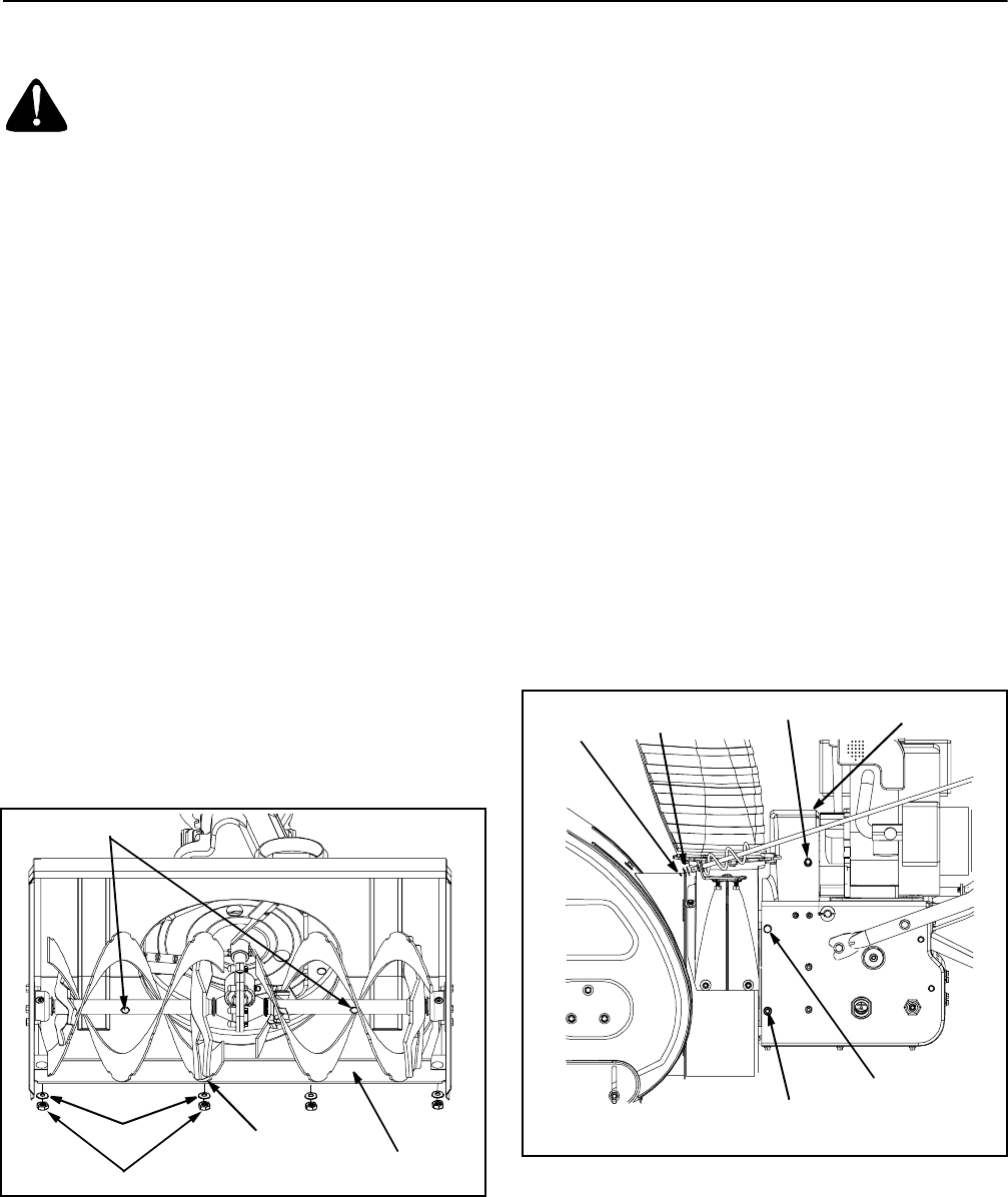
Figure 16
• Remove the six carriage bolts (three per side), bell
washers and hex nuts which attach skidskid shoes
to the snow thrower on either side. See Figure 12.
• Reassemble new skid shoes with the hardware
removed earlier (cupped side of bell washer against
the skid shoes). Make certain the skid shoes are
adjusted to be level. Refer to Figure 12.
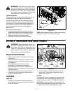
• To remove the shave plate, remove the carriage
bolts, bell washers and hex nuts which secure the
shave plate to the snow thrower housing. See
Figure 16.
• Reassemble the new shave plate, making sure
heads of carriage bolts are to the inside of the
housing.
• Reinstall the skid shoes and tighten securely.
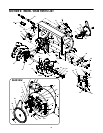
Replacing Belts
To remove and replace either the auger belt or the drive
belt, follow the steps below and then proceed to the
specific steps listed under respective sub-headings.
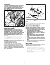
• Disconnect the chute crank assembly at the
discharge chute end by removing the hairpin clip
and the two flat washers.
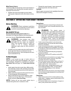
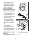
• Remove the plastic belt cover, located near the
engine, by removing the three self-tapping screws
and flat washers that secure it. See Figure 17.
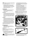
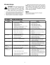
• Remove the large shoulder bolt and washer on the
left hand side of the engine pulley. See Figure 18.
Figure 17
Shear Bolts
Carriage Bolt
Hex Nut
Washer
Shave Plate
Upper Bolt
(remove)
Hairpin
Clip
Flat
Belt Cover
Belt Cover Bolts(3)
Shoulder Bolt
(do not remove)
Washers