


11
• Thread the lock nut outward (down the coupler)
three full turns to provide more slack in the cable
and reattach the spring to the bracket.
• Check the adjustment of the traction control as
instructed earlier. Repeat the previous steps to
provide more slack in the cable, in necessary.
If you are uncertain that you have reached the correct
adjustment, proceed as follows:
WARNING: Drain the gasoline out of your
snow thrower’s engine, and place a piece of
plastic film under the gas cap to avoid spillage
before beginning the job.
• Tip the snow thrower forward, allowing it to rest on
the auger housing.
• Remove the frame cover underneath the snow
thrower by removing six self-tapping screws.
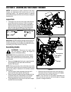
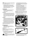
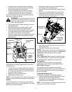
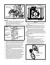
• With the traction control released, make sure there
is clearance between the friction wheel and the
drive plate in all positions of the shift lever.
• With the traction control lever engaged, make sure
the friction wheel solidly contacts the drive plate.
See Figure 10.
Figure 10
If adjustment is necessary, adjust traction control as
instructed below:
• Thread the lock nut outward (down the coupler) to
provide more slack in the cable or thread the lock
nut inward (up the coupler) to provide less slack in
the cable. Refer to Figure 9
• Reattach the spring to the bracket.
• Reassemble the frame cover.
NOTE: If you placed plastic film under the gas cap, be
certain to remove it before operating the snow thrower.
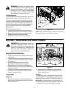
Shift Rod
If your snow thrower is not achieving its full range of
speeds, the shift rod is in need of adjustment. To adjust
the shift rod, proceed as follows:
• Remove the hairpin clip and flat washer from the
shift handle under the handle panel.
• Place shift lever in sixth (6) position (fastest forward
speed).
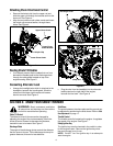
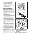
• Push shift arm assembly down as far as it will go.
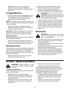
• Rotate the ferrule up or down on the shift rod as
necessary until the ferrule lines up with the upper
hole in the shift lever. See Figure 11.
Figure 11
• Insert ferrule from the left side of the snow thrower
into the upper hole.
• Reinstall the hairpin clip and the washer.
NOTE: Make certain to check for correct adjustment
of the shift rod as instructed on page 10—Traction Control
and Shift Lever before operating the snow thrower.
Auger Control
Refer to Auger Control Test on page 9 to adjust the auger
control. Make certain to check for correct adjustment
as instructed before operating the snow thrower.
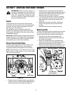
Chute Assembly
The distance snow is thrown can be adjusted by
adjusting the angle of the chute assembly. Refer to
Chute Tilt Control on page 6.
The remote chute control cables have been pre-
adjusted at the factory. Move the remote chute lever on
the control panel back and forward to adjust angle of
the chute assembly.
Tire Pressure (Pneumatic Tires)
The tires are overinflated for shipping purposes.
• Check the tire pressure before operating the snow
thrower. Refer to the tire side wall for tire
manufacturer’s recommended psi and deflate (or
inflate) the tires as necessary.
NOTE: If the tire pressure is not equal in both tires, the
unit may pull to one side or the other.
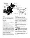
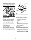
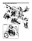
Trigger Cables
Shift Arm
Drive Actuator
Auger Actuator
Hex Nut
Hex Gear Shaft
Drive Plate
Rubber
Bracket
Bracket
And Cupped
Washer
Friction
Wheel
Shift Lever
Ferrule
Shift Arm
Lower Shift Rod
Clutch Rod
Connector
Hairpin Clip &
Flat Washer