


5
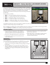
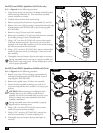
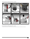
Connecting Control Wires to the INFINITY Series with Satellite
e eld satellite controllers provide a 24 VAC
signal to the sprinklers typically using individual
wires. Connections to the sprinkler solenoid in
these systems are not polarity sensitive and do
not require specic wire connections. Typically
the “common” wire from the controller is daisy-
chained to multiple sprinklers with one wire
coming in from the satellite or closer sprinkler
and the other going on to the next sprinkler. e
station output “hot” wire typically connects to a
single sprinkler but can also be daisy-chained to
multiple sprinklers depending upon the control
system capabilities.
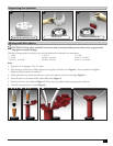
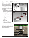
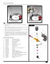
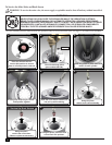
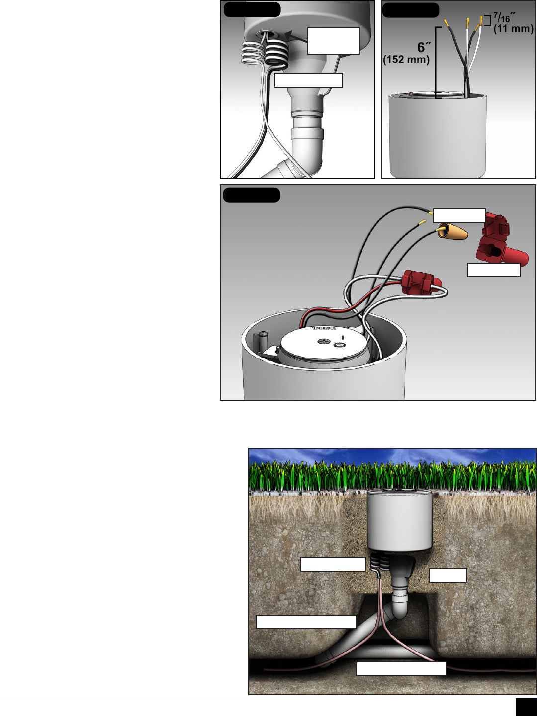
1. Route all wire(s) through the access grommet
in the bottom of the sprinkler compartment
providing a service loop below the sprinkler
to allow for height adjustment and future
servicing. (See Figure 1.)
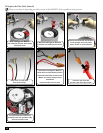
2. Pull all wire(s) out the top of the sprinkler
approximately 6˝ (152 mm). (See Figure 2.)
3. Remove 7/16˝ (11 mm) of the insulation from
all of the control wires. (See Figure 2.)
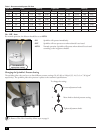
4. Connect the “common” wire(s) to one of the
solenoid wires with a wire nut and install into
a waterproof grease cap (both provided).
(See Figure 3.)
5. Repeat for the station output “hot” wire(s).
(See Figure 3.)
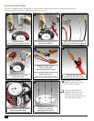
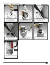
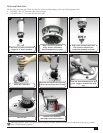
6. Fold and tuck the wire connections into the
compartment pocket.
7. Replace cover and install the three (3) cover
screws (from accessory kit). Tighten to 25 in/
lb. (34,6 kilogram force meters) max or
medium torque setting on a battery-powered drill.
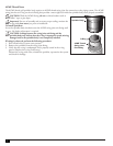
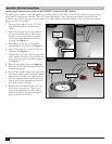
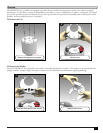
Final Adjustments
Adjust the swing joint to bring the top of the sprinkler
ush to grade. Back ll with clean porous material that
promotes drainage. Tamp the soil around the sprinkler to
compact the soil and prevent settling.
Figure 2
Figure 3
grease cap
wire nut
Figure 1
service loops
access
grommet
Toro swing joint
mainline/lateral
sand
service loops