


4
Sprinkler Wiring Connections
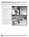
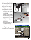
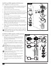
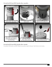
Connecting Communication Cable to the INFINITY Series with GDC Module
e GDC system provides a coded DC signal over a polarity sensitive color coded communication cable that requires correct
connections to ensure proper operation. e GDC system also employs a daisy chain communication network where all
sprinklers, except the last one on a wire run, will have one cable coming in from the Gateway or closer sprinkler and another
going out to the next sprinkler.
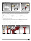
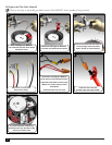
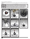
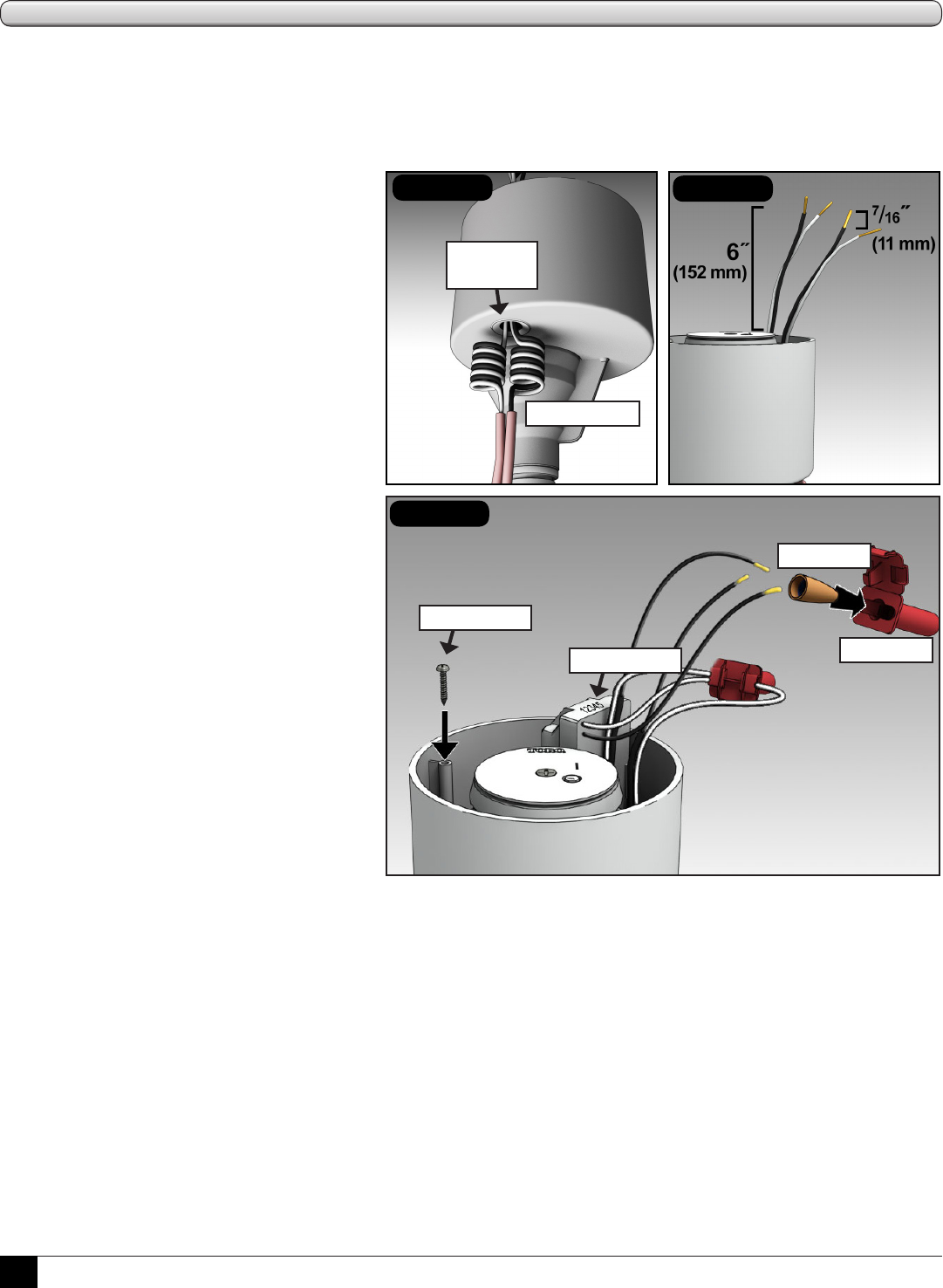
1. If using jacketed cable, remove ~20” (508
mm) of shielding from communication
cable(s).
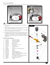
2. Route wires through the access grommet in
the bottom of the sprinkler compartment.
Provide a service loop below the sprinkler
to allow for height adjustment and future
servicing. (See Figure 1.)
3. Pull cable(s) out the top of the sprinkler
approximately 6˝ (152 mm). (See Figure 2.)
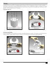
4. Strip 12-16 gauge wires 7/16˝ (11 mm) of
insulation. (See Figure 2.)
5. Connect the white cable wire(s) and the white
GDC module wire with a wire nut and install
into a waterproof grease cap (both provided).
(See Figure 3.)
6. Repeat for the black wire(s). (See Figure 3.)
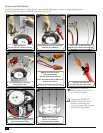
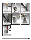
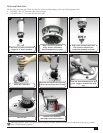
7. Fold and tuck the cable connections into the
compartment pocket.
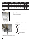
8. Record GDC module address and reference to
site location. Remove the 2 additional address
labels from the accessory kit. Ax one to the
cover for temporary future reference and the
other to the location identication form for
entry at the central controller.
9. Replace cover and install the three (3) cover
screws (from accessory kit). Tighten to 25
in/lb. (34,6 kilogram force meters) max or
medium torque and low speed setting on a
battery-powered screw-driver.
Figure 2
Figure 3
grease cap
wire nut
Figure 1
service loops
address label
access
grommet
spare screw