


12
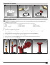
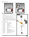
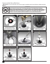
For INF34 and INF54 Sprinklers (Full Circle only)
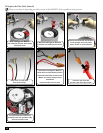
Refer to Figure 8 for the following procedure.
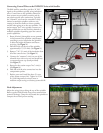
1. Grasp return spring (14) and riser (16) rmly and hold in place
while removing nozzle base (4). Turn nozzle base assembly
counter-clockwise to remove.
2. Carefully release tension from return spring.
3. Remove spring and seal retainer/o-ring assembly (12 and 13).
4. Remove riser screen (19) by turning it counterclockwise with edge
of multi-purpose tool (P/N 995-83) or tips of snap ring pliers
(P/N 995-100).
5. Remove o-ring (15) from top of riser assembly.
6. Remove drive assembly (17) and stator (18) from riser assembly
by carefully pressing on end of threaded shaft.
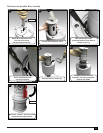
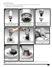
7. Using a 5/8” nut driver (P/N 995-99), unscrew main nozzle
(10) from nozzle housing (8). e riser cap (3) must still be
attached to the nozzle base assembly (4), or the nozzle housing
(8) will turn instead of the main nozzle.
8. Using a 5/16” nut driver (P/N 995-105), unscrew intermediate
nozzle (6) and inner nozzle (5) and plugs (7) from the nozzle
base assembly.
9. oroughly clean and inspect all parts and replace as necessary.
During reassembly, ensure snap ring is correctly installed and
fully seated in snap ring groove. Use the Multipurpose tool to
assist in proper placement.
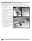
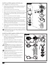
For INF35 and INF55 Sprinklers (Full/Partial Circle)
Refer to Figure 9 for the following procedure.
1. Remove riser screen (17) by turning it counterclockwise
with edge of multi-purpose tool (P/N 995-83) or tips of
snap ring pliers (P/N 995-100).
2. Remove the variable stator (16) from riser assembly.
3. Loosen the drive assembly retaining screw (14) six or
seven turns and pull the drive assembly (15) using a pair
of pliers.
!
CAUTION: When removing or installing the drive
assembly, do not use the turbine to pull the drive
assembly. Use the drive assembly body to extract it out.
Failure to comply may cause separation of the drive
assembly components.
During reassembly, ensure drive assembly is properly
aligned with the retaining screw.
4. Using a 5/8” nut driver (P/N 995-99), unscrew main
nozzle (9) from nozzle base assembly.
5. Using a 5/16” nut driver (P/N 995-105), unscrew the
inner (8), intermediate (7) nozzles, and plug (12).
6. oroughly clean and inspect all parts and replace as
necessary.
1
2
3
5
6
4
7
8
9
10
11
12
13
14
15
16
17
18
19
7
Figure 8
2
13
15
16
17
1
3
4
5
6
12
14
8
10
11
9
7
Figure 9