


Servicing Main Valve
WARNING! If the valve snap ring is difficult to remove, residual water pressure may be remaining in the system.
To prevent possible serious injury due to valve being ejected upward under pressure, confirm the following
conditions exist prior to removing the snap ring and valve.
A. Water supply to sprinkler is shut off at source.
B. All pressure is bled from system, including control tubes.
C. AC power is disconnected at source.
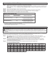
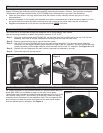
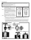
Step 1 – See WARNING above. To remove valve assembly,
squeeze snap ring ears together with snap ring
pliers (P/N 995-100) and remove snap ring from
sprinkler body. See Figure 7.
Step 2 – Use valve removal tool P/N 995-08 for FLX34
or 995-09 for FLX54 to remove valve assembly
from base of sprinkler body. Valve removal tool is
inserted into sprinkler body and pushed through
valve ribs. A slight twist will catch tool under ribs
enabling valve removal by pulling straight up and
out. See Figure 8.
Note: If valve removal tool is not available, use
snap ring pliers to grasp rib of valve cylinder
assembly and pull up and out of sprinkler body.
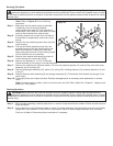
Step 3 – Reinstall valve assembly using valve insertion tool
P/N 995-76 for FLX34 or 995-101 for FLX54 as
follows:
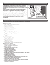
• Load snap ring onto insertion tool carrier with stepped side against carrier as shown in Figure 9. While
holding snap ring in compressed position, slide retainer clip in to hold snap ring ears
• Load valve assembly on carrier as shown.
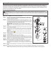
• Locate position of communication tube in bottom of sprinkler body and orient insertion tool accordingly.
• Insert tool straight down into sprinkler body aligning bosses on t-handle with holes on sprinkler body
flange. When valve assembly clears vertical side wall ribs inside body, pull up on snap ring release
mechanism (FLX54 models only) and press valve assembly into position. Snap ring will lock into groove
when properly installed. Remove insertion tool and check snap ring to confirm that it is fully seated in
groove.
Figure 8Figure 7
Snap Ring
Released
Press Valve Assembly
Into Position
Valve Assembly
Orientation In Carrier
Snap Ring In
Retainer Clip
Stepped Side
of Snap Ring
Snap Ring Release
Mechanism
Figure 9