


Servicing Procedures
The FLX34 and FLX54 series sprinklers are designed to provide the user trouble-free operation for many years without
scheduled maintenance. If it becomes necessary to disassemble the sprinkler to correct a malfunction or replace a
component, all internal parts of the sprinkler can be accessed from the top. Refer to the Troubleshooting Procedure in
this manual in the event of a malfunction. Some special tools are required for disassembly and/or maintenance of the
sprinkler and are available from your Toro dealer.
Servicing Sprinkler Mechanism
WARNING! Never stand or lean over the sprinkler while the irrigation system is being filled, during manual or
automatic operation or when performing sprinkler service procedures. Direct contact with irrigation spray, a failed
or improperly installed sprinkler connection or sprinkler components forcibly ejected upward under pressure can cause
serious injury.
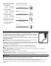
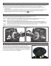
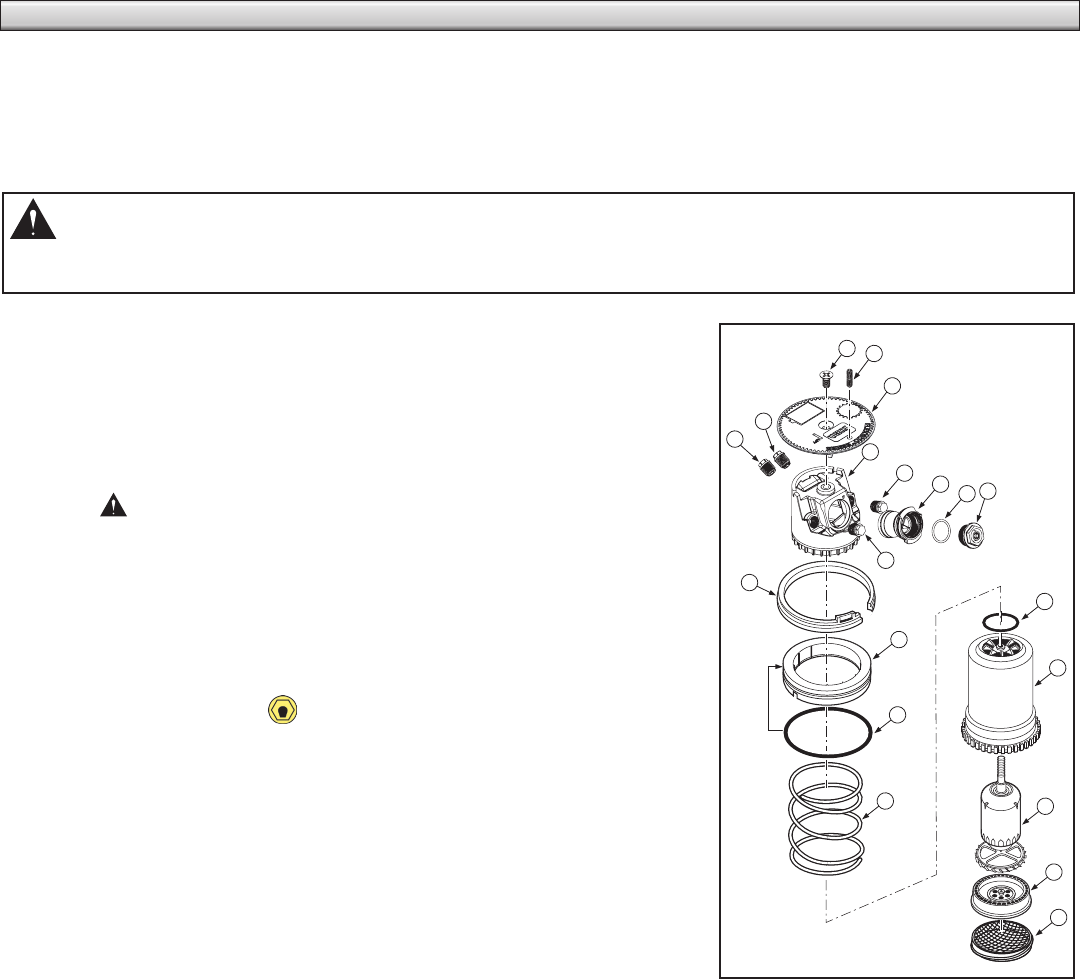
Note: Refer to Figure 6 for the following procedure.
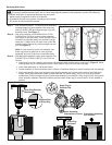
Step 1 – Insert the hooked end of the multi-purpose tool (P/N 995-83) into
the slot in the cap (3) and pull the riser assembly up until there is
enough clearance to handle.
Step 2 – Insert the hooked end of the tool into the snap ring slot (11). Pull
the snap ring inward towards the sprinkler assembly, then upward
to remove from the groove in body. Hold onto the riser body (16)
and carefully extract it from the sprinkler body.
CAUTION: The seal/retainer (12) will rapidly move upward
(caused by the decompressing spring [14]) as it clears the sprinkler
body.
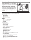
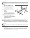
Step 3 – Using a 5/8" nut driver (P/N 995-99), unscrew main nozzle (10) from
main nozzle housing (8).
Step 4 – Using a 5/16" nut driver (P/N 995-105), unscrew the intermediate
nozzle (6) and inner nozzle (5) and plugs (7) from the nozzle base
assembly.
Note: During reassembly, ensure that the inner nozzle orifice is
aligned as shown.
Step 5 – Depress seal retainer (12) and spring (14), then remove cap screw
(1) and cap (3).
Step 6 – Carefully release tension from return spring.
Step 7 – Remove spring and seal retainer/o-ring assembly (12, 13 and 14).
Step 8 – Grasp the riser (16) firmly and hold in place while removing nozzle
base (4). Turn nozzle base assembly counter-clockwise to remove.
Step 9 – Remove o-ring (15) from top of riser assembly.
Step 10 – Three small tabs are provided on the edge of the multi-purpose
tool. Insert tabs into the debris filter screen (19). Holding the
plastic base of riser assembly, turn the screen counterclockwise to
remove.
Step 11 – Remove drive assembly (17) and stator (18) from riser assembly by carefully pressing on end of threaded
shaft.
Step 12 – Thoroughly clean and inspect all parts and replace as necessary. Reassemble in the reverse order.
Note: During reassembly, ensure snap ring is correctly installed and fully seated in snap ring groove.
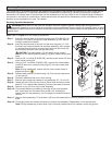
1
2
3
5
6
4
7
8
9
10
11
12
13
14
15
16
17
18
19
7
Figure 6