


11
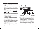
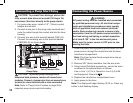
Connecting the Valves
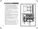
1. Route the valve wires or wire cable from the valves,
into the timer cabinet.
Note: The snap-in wire connectors accept 14–18
gauge (2mm
2
to 1mm
2
) wire. Using direct-burial irriga-
tion cable is recommended. Choose a cable that has
at least one more wire conductor than the number of
valves to be connected.
2. Attach the white color-coded wire to
either one of
the wires from each valve solenoid. This is called the
valve common wire.
3.
Attach an individual color-coded wire to the remaining
wire from each valve solenoid. Make a note of the wire
color used for each valve and the watering zone it
controls. You will need to have this information when
connecting the valve wires to the timer.
CAUTION: To prevent corrosion, connection fail-
ure and possible short circuit, use Toro waterproof
wire connectors (Model # 53687) or grease caps on all
exposed wire splice connections.
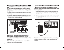
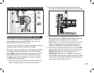
4. Route the wire cable into the timer through the large
opening in the base of the housing or through PVC
conduit (if it is installed). Strip insulation back 3/8″
(10mm) from all cable wires.
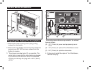
Note: The zone module has snap-in wire terminals.
To attach wires, simply raise the lever, insert the
stripped wire, and press the lever down to secure.
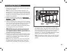
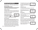
5.
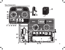
Referring to the Timer Components on page 5 and
the diagram above, secure the valve common wire to
the terminal labeled COM (10). Connect the individual
zone valve wires to the appropriate zone module
terminals (11). Connect the master valve wire (if appli-
cable) to the terminal labeled PUMP/MV (9).
Note: Connecting a master valve or pump start relay
is optional and may not be required in your sprinkler
system.
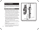
Valve Common
Wire
Zone
Valves
Master
Valve
11
10
9