


Reelmaster 7000 Hydraulic SystemPage 4 -- 51
Themowcircuitreliefpressuretestshould beperformed
to make sure that the mow circuit relief pressures are
correct.
Procedure for Mow Circuit Relief Pressure Test
1. Make sure hydraulic oil is at normal operating tem-
peraturebyoperatingthemachineforapproximatelyten
(10) minutes. Make sure the hydraulic tank is full.
2. Parkmachine onalevel surfacewith thecuttingunits
lowered and off. Make sure engine is offand the parking
brake is engaged. Also,make sure that the backlap lev-
ers on the mow control manifold are in the mow position
(F on the manifold).
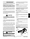
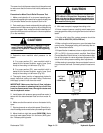
CAUTION
Prevent personal injury and/or damage to equip-
ment. Read all WARNINGS, CAUTIONS and Pre-
cautions for Hydraulic Testing at the beginning
of this section.
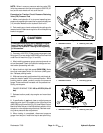
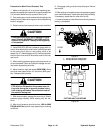
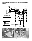
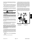
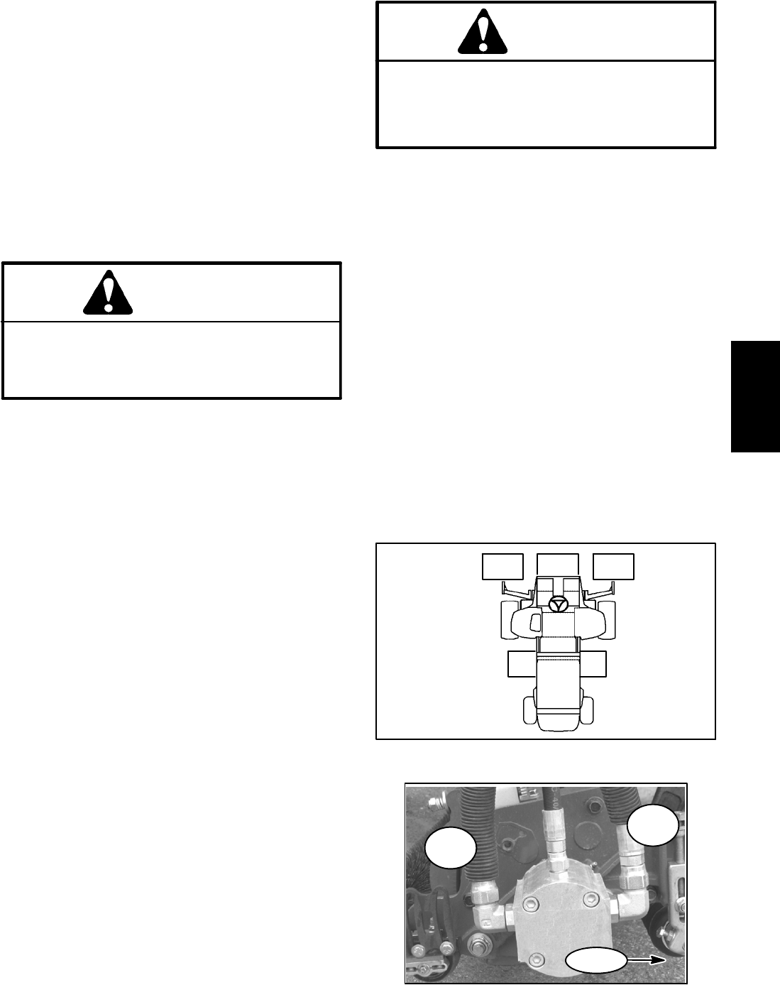
3. Determine mow manifold relief pressure to be
tested:
A. For pump section (P1), mow manifold relief is
tested at the forward direction supply hose (front
hose) to the cutting unit #4 motor (Fig. 39).
B. For pump section (P2), mow manifold relief is
tested at the forward direction supply hose (front
hose) to the cutting unit #2 motor (Fig. 39).
4. Thoroughly clean junction of appropriate hydraulic
supply hose and cutting unit motor fitting. Disconnect
the supply hydraulic hose from the motor.
IMPORTANT: Make sure that the oil flow indicator
arrow on the tester is showing that the oil will flow
from the disconnected hose, through thetester and
into the hydraulic motor.
5. Install tester with pressure gauge and flow meter in
series with the disconnected hose and front motor fit-
ting.
6. Make sure the flow control valve on the tester is fully
open.
7. Start engine and run at low idlespeed. Check for hy-
draulic leakage and correct before proceedingwith test.
8. Move throttle to high idle speed (2850 RPM).Make
sure that mow speed limiter is in the mow (4WD) posi-
tion. Release parking brake.
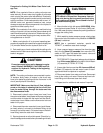
CAUTION
Cutting reel blades will rotatewhen loweredwith
PTO switch in ON position. Keep away from cut-
ting units during test to prevent personal injury
from rotating reel blades. Do not stand in front of
the machine during test.
9. With seat occupied, engage the cutting units.
10.Have a second person carefully watch tester pres-
suregauge whileslowly closingtheflow controlvalve on
tester.
11.As the relief valve lifts, system pressure should be
from 2800 to 3200 PSI (193 to 220 bar).
12.After noting the relief pressure, open the tester flow
control valve, disengage cutting units and stop the en-
gine. Record test results.
13.If specificationis notmet, clean oradjust relief v alve
(RV1 or RV2) in the mow control manifold. See Adjust
Control Manifold Relief Valves in the Adjustments sec-
tion of this chapter for valve adjustment procedure. Re-
check relief valve pressure setting after adjustment.
14.After testing is complete, disconnect tester from cut-
ting unitmotor and hose.Connect hydraulic hose tomo-
tor.
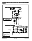
Figure 39
#4 #1 #5
CUTTING
UNIT
LOCATIONS
#2 #3
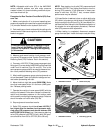
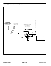
Figure 40
RETURN
HOSE
SUPPLY
HOSE
FRONT
Hydraulic
System