


Reelmaster 7000Page 5 -- 24Electrical System
Engine Cooling Fan Switch
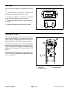
The engine cooling fan switch is located on the outside
of the console arm (Fig. 30). This two (2) position rocker
switchallows theengine coolingfan torun inthenormal,
automatic mode or in the manual reverse (momentary)
direction.
Testing
1. Before disconnecting the engine cooling fan switch
for testing, the switch and its circuit wiring should be
tested as a TEC input with the Diagnostic Display (see
DiagnosticDisplay inthe Troubleshootingsectionofthis
chapter). If the Diagnostic Display verifies that cooling
fan switch andcircuit wiring are functioning correctly, no
further switch testing is necessary. If, however, the Dis-
playdetermines thatcoolingfanswitch andcircuitwiring
are not functioning correctly, proceed with test.
2. Make sure ignition switch is OFF. Remove key from
ignition switch.
3. Disassemble console arm to gain access to the en-
gine cooling fan switch (see Console Arm Disassembly
in the Service and Repairssection of Chapter 7 -- C has-
sis).
4. Disconnect harness electrical connector from the
cooling fan switch.
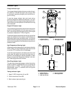
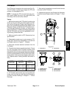
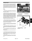
5. With the use of a multimeter (ohms setting), the
switch functions may be tested to determine whether
continuity exists between the various terminals for each
position. The switch terminals are marked as shown in
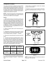
Figure 31. The circuitry of the cooling fan switch is
shown in the chart below. Verify continuity between
switch terminals.
SWITCH
POSITION
NORMAL
CIRCUITS
OTHER
CIRCUITS
AUTO 2+3 5+6
MANUAL RE-
VERSE
2+1 5+4
6. If switch tests correctly and circuit problem still ex-
ists, check wire harness (see ElectricalSchematics and
Wire Harness Drawings in Chapter 9 -- Foldout Draw-
ings).
7. After testing is completed, connect wire harness
connector to the cooling fan switch.
8. Assemble console arm (see Console Arm Assembly
in the Service and Repairssection of Chapter 7 -- C has-
sis).
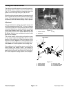
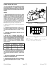
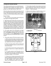
1. Console arm 2. Cooling fan switch
Figure 30
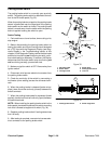
2
1
Figure 31
BACK OF SWITCH
NOTE: Cooling fan switch terminals 3, 4, 5 and 6 are
not used on Reelmaster 7000 machines.