


Reelmaster 7000 Hydraulic SystemPage 4 -- 21
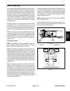
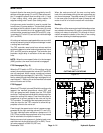
Mow Circuit
Hydraulic flow for the mow circuit is supplied by two (2)
sections of the gear pump (P1 andP2). Gear pump sec-
tion P1 supplies hydraulic flow to cutting units 1, 4 and
5 (front cutting units), while gear pump section P2
supplies cutting units 2 and 3 (rear cutting units).
A single mow control manifold is used to control flow
from the two (2) pump sections. The manifold includes
cartridge valves for control of each of the two (2) pump
circuits. Each manifold circuit is equipped with a s ole-
noidcontrolled,proportionalvalve( SP1 andSP2),alog-
ic cartridge (LC1 and LC2) and a circuit relief cartridge
(RV1 and RV2).
Allcuttingreelmotorsareequippedwithcrossoverrelief
valves to prevent hydraulic component damage in case
a cutting reel should stall.
The TEC controller uses inputs from v arious machine
switches to determinewhen solenoid proportional valve
(SP1 and SP2) are to be energized. The controller also
provides a slight delay in activation of the rear cutting
units.
NOTE: When the mow speed limiter is in the transport
(2WD) position, the mow circuit c annot be engaged.
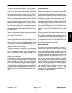
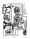
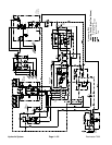
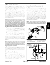
PTO Disengaged (Fig. 15)
When the PTO switch is OFF (or if the cutting units are
raised), themanifold proportionalvalves (SP1 andSP2)
are not energized, which causes a pressure increase
that shiftsthe logic cartridges (LC1and LC2). Thepump
flow is routed through the shifted logic cartridge and out
manifold portT1. Returnoil from themanifold isdirected
to the oil cooler and oil filter.
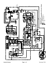
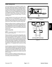
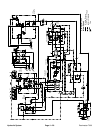
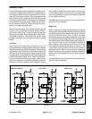
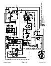
PTO Engaged
When the PTO switch is turned ON with the cutting units
lowered, the manifold proportional valves (SP1 and
SP2) are energized with outputs from the TEC--5002
controller.Theenergizedvalves shifttodirectpump flow
toward the cutting unit motors. Flow from the valves is
proportional to current applied to the valve coil by the
TEC controller. The settingof thereel speed controlpro-
vides the input for the TEC controller to allow the ap-
propriate current to the valve coil.
Flow through the speed control valve is pressure com-
pensated by the logic cartridge valves (LC1 and LC2).
The logic c artridge valve maintains a pressure of 110
PSI (7.6 bar) across the proportional valve. Any excess
flow is returned to the hydraulic reservoir.
Maximum mow circuit pressure is limited at each mow
manifold circuit by the reliefvalve (RV1 or RV2). The re-
lief valve pressure is 3000 PSI (207 bar).
When the reels are shut off, the over--running inertia
load of the reels keeps driving the reel motors and can
turn them into pumps. The check valves (CV1 and CV2)
in the mow control manifold will open to keep the reel
motor circuit full of oil so the motors will not cavitate.
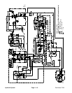
Backlap
When either ofthe mow controlmanifold backlap valves
are rotated to the backlap (R) position, pump flow to the
cutting unit motors is reversed. This change in flow di-
rection reverses the rotation of the front or rear cutting
reel motors allowing the backlap operation.
Figure 14
CUTTING UNIT LOCATIONS
#4 #1 #5
#3#2
Figure 15
P1 T2 T1 P2
RV2
SP1
SP2
LC2
LC1
RV1
M5
CV1
M1M4
OR1
OR2
CV2
M3M2
MV1
MV2
M3M4M1 M2
MOW
MANIFOLD
CONTROL
FROMGEAR
PUMPP1
FROMGEAR
PUMPP2
Hydraulic
System