


Reelmaster 7000 Page 6 -- 5 Axles, Planetaries and Brakes
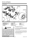
5. Remove hydraulic wheel motor (see Front Wheel
Motors in Service and Repairs section of Chapter 4 --
Hydraulic System).
6. Disconnect brake cable from pull rod on brake.
NOTE: Be careful to not drop splined brake shaft as
brake assembly is removed.
7. Support brake assembly and remove flange head
cap screws (item11)securing brake assemblyto frame.
Remove brake assembly.
8. Remove splined brake shaft.
9. Completebrake inspection and repair (seeBrake In-
spection and Repair in this section).
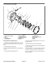
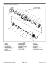
Brake Assembly Installation (Fig. 1)
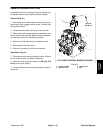
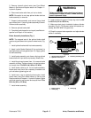
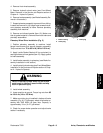
NOTE: The stepped end of the splined brake shaft
must be aligned toward the hydraulic wheel motor (Fig.
2).
1. Install splined brake shaft into brake assembly.
2. Apply Loctite Gasket Sealant #2 (or equivalent) to
sealing surfaces of new gasket (item 19). Apply gasket
to brake assembly.
3. Install brake assembly onto frame, aligning splined
brake shaft with input shaft on planetary wheel drive.
4. Install flange head screws (item 11) to secure brake
assembly to frame.Tightenscrews in a crossing pattern
to a torque from 75 to 85 ft--lb (102 to 115 N--m).
5. Install brake cable to pull rod on brake assembly.
Brake cable end should be completely threaded onto
pull rod before tightening jam nut.
6. Install new o--ring on hydraulic wheel motor. Install
wheel motor (see Front Wheel Motors in Service and
Repairssection ofChapter4 -- H ydraulic System).Make
sure that mounting c ap screws are torqued from 75 to
85 ft--lb (102 to 115 N--m).
7. Install wheel assembly.
Failure to maintain proper wheel lug nut torque
could result in failure or loss of wheel and may
result in personal injury.
WARNING
8. Lower machine to ground. Torque lug nuts from 85
to 100 ft --lb (116 to 135 N--m).
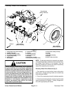
9. Make sure drain plug is installed in bottom of brake
assembly (Fig. 3). Fill planetary wheel drive/brake as-
sembly with SAE 85W--140 gear lube.
10.Check for proper brake operation and adjust brake
cables if necessary.
1. Splined brake shaft step
2. Hydraulic motor end
3. Planetary assembly end
Figure 2
3
1
2
1. Brake housing
2. Check plug
3. Drain plug
Figure 3
2
1
3
Axles, Planetaries
and Brakes