


Assembly Section 2-5
ASSEMBLY
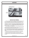
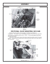
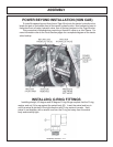
SWITCH BOX WIRING
The floor covering will need to be removed to route the wires to the front console
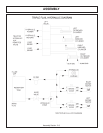
panel. Refer to the parts section for wiring diagram to hook up the switch box.
Cover the four wires from the switch box with plastic wire wrap provided. Route the
wires from the switch box down to the floor and under the floor matt to the front
console panel. From there, run the wires with the existing wires that go to the front
console panel. Remove the console panel under the steering wheel to access wires.
Locate the brown colored wire. Using a test light or meter to verify this wire is
the neutral safety wire. Cut the brown wire and connect the green wires from the
switch box as shown in the wiring diagram.
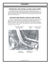
To run the white wire to the solenoid valve, you will need to drill a hole in the front
edge of the cab floor to the right of the front console. Insert a rubber grommet into
the hole to protect the wire, and route the wire out of the cab.
The red wire is to be hooked to the tractor ignition switch or an available slot in the
fuse box. NOTE: Be certain that the power taken for the switch box is “HOT”
only when the tractor ignition is “ON”. Also double check that the line is
fused.
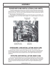
The travel lock red wire from the switch box should also be covered with wire
wrap and should run with the white wire through the grommet. This wire will be
connected to the electronic travel lock located on the main boom cylinder.
The wires from the switch box are longer than needed and should carefully cut
and spliced as required. Zip ties should be used to secure the wires to the tractor
framework.
12-10-01