


Assembly Section 5-2
TRIPLE EGRESS MOUNTING
Park the tractor on a flat, hard, level surface. Lower both side decks down onto the
hard surface. Make sure the engine is off and the park brake has been set. Operate the
lift controls several times to release any pressure contained in the hydraulic lift system.
Disconnect the positive battery cable from the battery. Then remove the right rear
wheel from the tractor. Next remove the left side deck lift hoses from the lift valve and
both lift cylinders, mark or label valve ports and cylinders as hoses are removed.
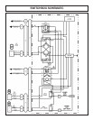
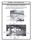
Refer to the Parts Section for illustrated assemblies, and wiring diagram for the
triple egress. Install the egress switch box brackets on the left side of the mower pump
mounting bracket, using hardware supplied. See pictures on next page. After the bracket
is secured, then remove the front cover from the switch box, and install the switch box
back half to the switch box bracket with (4) 8/32 x 1/2” machine screws. Reinstall the
front cover onto the switch box.
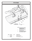
Install the egress pump mounting bracket onto the right side of the tractor located
under the cab in front of the right rear axle using hardware provided. Next preassemble
the rear half of the pump cover onto the egress pump with the hardware provided, do
not tighten bolt at this time. Connect the hoses for the C1 port to the egress pump port
only. Do not tighten hoses at this time. The pump is now ready to be mounted to the
pump mounting bracket. Secure egress pump to the bracket with the hardware provided.
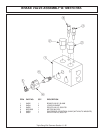
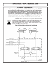
Locate the ports on the egress pump labeled “A1”, “A2”, “B1”, “B2”, “C1” and “C2”,
these ports will be the connection points for the hydraulic lift lines.
A1 port - to lift valve -- left hand outboard cylinder gland
A2 port - to cylinder -- left hand outboard cylinder gland
B1 port - to lift valve -- left hand outboard cylinder butt
B2 port - to cylinder -- left hand outboard cylinder butt
C1 port - to lift valve -- left hand inboard cylinder gland
C2 port - to cylinder -- left hand inboard cylinder gland
Route the hoses to the lift valve and or cylinder as specified above, tighten all hose
fittings. Refer to the Parts section for the location of hose connections on the lift valve.
Now that the hydraulic lines are installed, connect the power cable from the positive
post of the egress pump solenoid to the tractor starter solenoid positive post. Also
connect the ground cable from the negative post on the egress pump electric motor to
a bracket mounting bolt on the frame. Then route the cable from the switch box along
the tractor to the egress pump and connect the male to the female plug. Secure cable
with cable tie.
Next remove the drain plug on the bottom of the tractors transmission, CAUTION
hydraulic oil will come out and maybe hot. Oil loss can be reduced by attaching a shop
vacuum to the tractor transmission fill neck. Install fittings into the transmission drain
hole, refer to part section for parts and illustrations. Connect the suction hose from the
filter to the fittings on the tractor transmission, cut the hose to the required length. Install
a hose clamp both end of the hose.
Install the front half of the cover onto the egress pump with provided hardware.
Make sure all mounting hardware and hose connections are tight. Check hydraulic oil
level and add if required. Reinstall the right rear wheel and reconnect the positive battery
cable to the battery.
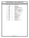
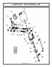
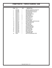
ASSEMBLY - TRIPLE EGRESS, CAB