


Assembly Section 2-8
ASSEMBLY
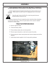
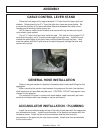
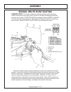
CABLE CONTROL LEVER STAND
Place the front edge of the support bracket 2 ¾” back from the lower right front
window. Rotate stand to be 2 ¼” from the right door frame as shown below. Be
sure that the location of the stand will allow clearance between the cable control
handles and all existing interior levers, etc.
Drill 3 holes to match control bracket and secure with cap-screws and nylock
nuts noted in parts section.
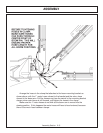
Cut a 2 ¼” hole in the floor from inside the cab. This hole is to be located 2 1/2”
away from the edge, and 4” from the metal edge by the right door. Install trim lock
around the metal edges of the hole, then route the cables through the hole. Next,
wrap the cables with the 6” split hose at the point they pass through the hole, and
secure with zip-ties.
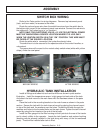
GENERAL HOSE INSTALLATION
Refer to the parts section for detailed information about hoses and fittings for this
application.
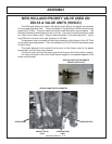
When mounting the suction hose between the pump and the tank, the stainless
steel bands that are provided must be used. CAUTION: DO NOT use regular hose
clamps for this purpose.
For protection of hoses in contact with metal edges, wrap hoses with spit hose
sections and fasten with hose clamps or zip ties as needed.
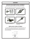
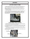
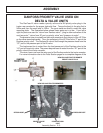
ACCUMULATOR INSTALLATION / PLUMBING
Install the accumulator bracket on top of the main frame mast with the capscrews
and lockwashers shown. Install the accumulator in the bracket and secure with the
hardware shown. Install the tee on the accumulator and the hose from the
accumulator to the gland on the main boom cylinder. Install hose from accumulator
to the control valve.