


Assembly Section 2-7
ASSEMBLY
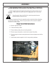
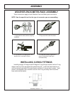
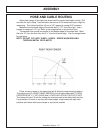
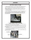
HOSE AND CABLE ROUTING
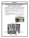
Attach two clamps to the right rear wheel well for proper hose/cable routing. Drill
one hole for each clamp. Use the lower rear corner of the wheel well as an origin for
measuring. The holes should be 10mm or 3/8” reamed to accept 3/8” hardware.
Measure from the back edge of the wheel well 13-1/2” from the origin. Use a
square to measure 3-1/2” up. Refer to the image below to see the first hole.
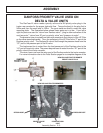
The second hole should run parallel to the bottom edge of the wheel well. Mark
the hole 12” from the first hole and 3 ½” from the bottom edge. Use the image below
for reference.
NOTE: DO NOT CUT INTO TUBES / HOSES / WIRES WHEN DRILLING
THROUGH METAL OR PLASTIC!
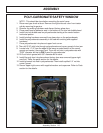
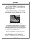
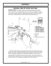
Place as many hoses in the clamp that will fit without compromising pressure.
Then secure the (2) HOSE CLAMP (06520013) to the holes drilled with (1 EACH)
CAPSCREW,3/8” X 1”,NC (21630) and (1 EACH) NYLOCK NUT,3/8”,NC (21627).
The hoses that don’t fit into the clamp are to be secured to the others with zip-ties.
For protection of hoses in contact with metal edges, wrap hoses with spit hose
sections and fasten with hose clamps or zip ties as needed.