


Operation Section 4-9
OPERATION
RBF-19C 07/04
© 2004 Alamo Group Inc.
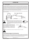
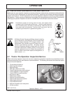
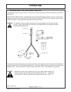
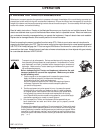
5. CONNECTING ATTACHING HEAD TO THE BOOM
The rotor unit can now be fitted to the end of the arms.
The illustration shows the Rhino 1948 cowl bracket.
Start the tractor engine and raise the second arm so
that the mower head clamp is approximately 300mm
(18 in.) clear of the ground. Place the mower head
directly in front of the second arm. Level up mower
head with wood packing. Remove clamp bracket (A)
from the end of arms. Adjust position of the arms until
the mower head clamp is lined up with the clamping
bar on top of the rotor unit in the desired position along
the bar. Replace clamp bracket (A) and nut and
washers (B). Tighten fully. Note: Additional support
may be needed at the end of the Boom to aid in
installation.
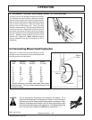
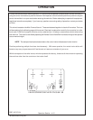
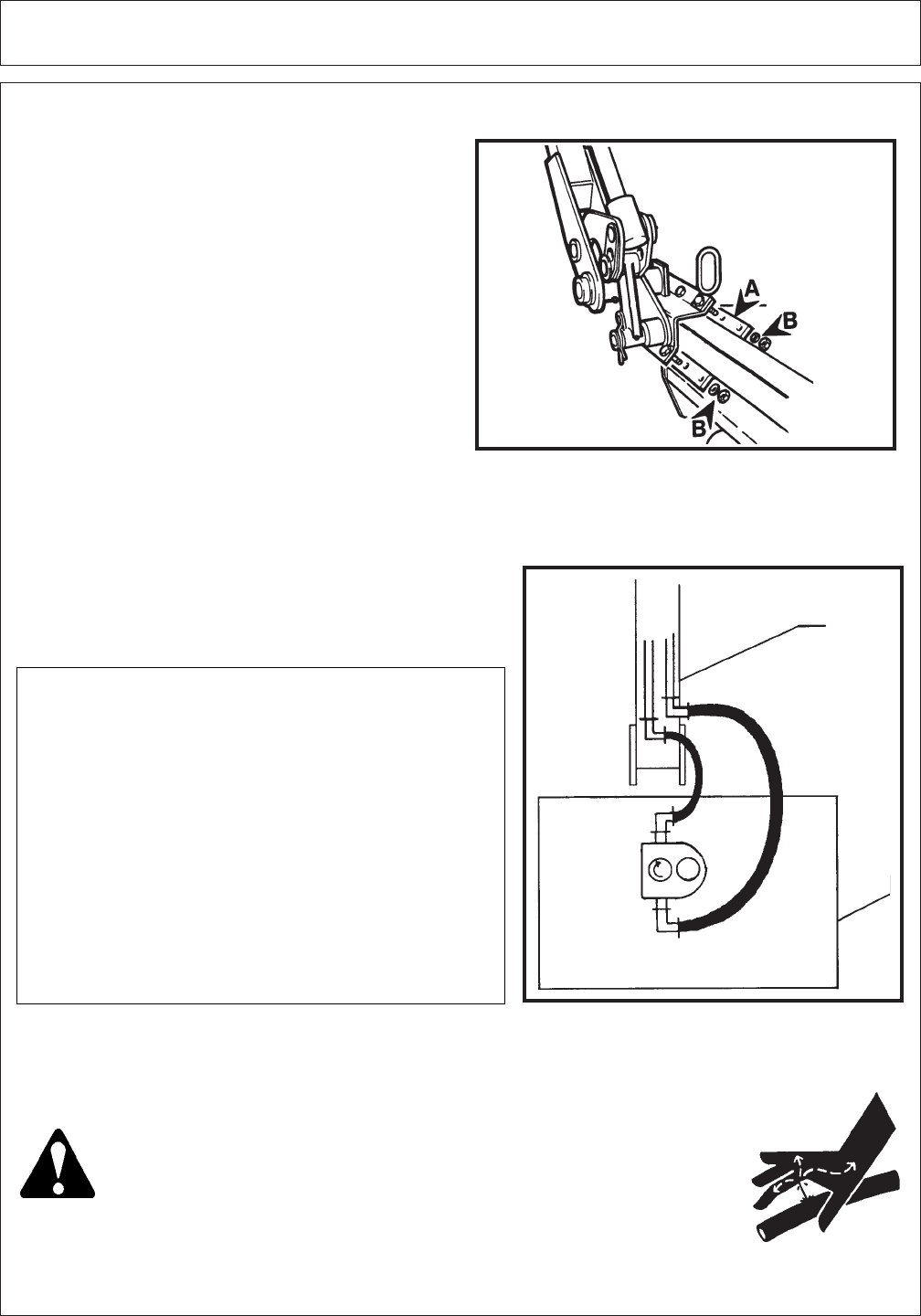
5.2 Connecting Mower Head Hydraulics
Attach the 1" hoses, from the articulating arm to the
hydraulic motor on the head. Use recommended hose
end torque values in chart below.
* Straight threads do not always seal better when higher
torques are used. Too much torque causes distortion and
may lead to leakage.
VALUE*
(FT.LBS.)
12
19
38
54
75
100
133
167
233
TORQUE
(IN.LBS.)
140
230
450
650
900
1200
1600
2000
2800
NOMINAL
SIZE (IN.)
1/4
3/8
1/2
5/8
3/4
1
1-1/4
1-1/2
2
DASH
SIZE
-4
-6
-8
-10
-12
-16
-20
-24
-32
DANGER! Do not operate this Equipment with hydraulic oil leaking. Oil is
expensive and leaking oil could present a hazard. Do not check for
leaks with your hand! Use a piece of heavy paper or cardboard. High-
pressure oil streams from breaks in the line could penetrate the skin
and cause tissue damage including gangrene. If oil does penetrate the
skin, have the injury treated immediately by a physician. (SG-15)
Boom
End
Head
Return
Pressure