


STOW G-4.5R A.C. GENERATOR — OPERATION & PARTS MANUAL — REV. #3 (03/13/06) — PAGE 29
STOW G-4.5R — INITIAL START-UP ENGINE/OPERATION
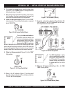
Stopping The Engine
Normal Shutdown
1. Place the
main circuit breaker
(Figure 11) in the OFF
position.
2. Remove the load from the generator, and let the engine
run at idle for 3-5 minutes with the idle control switch in
the ON position (Up)
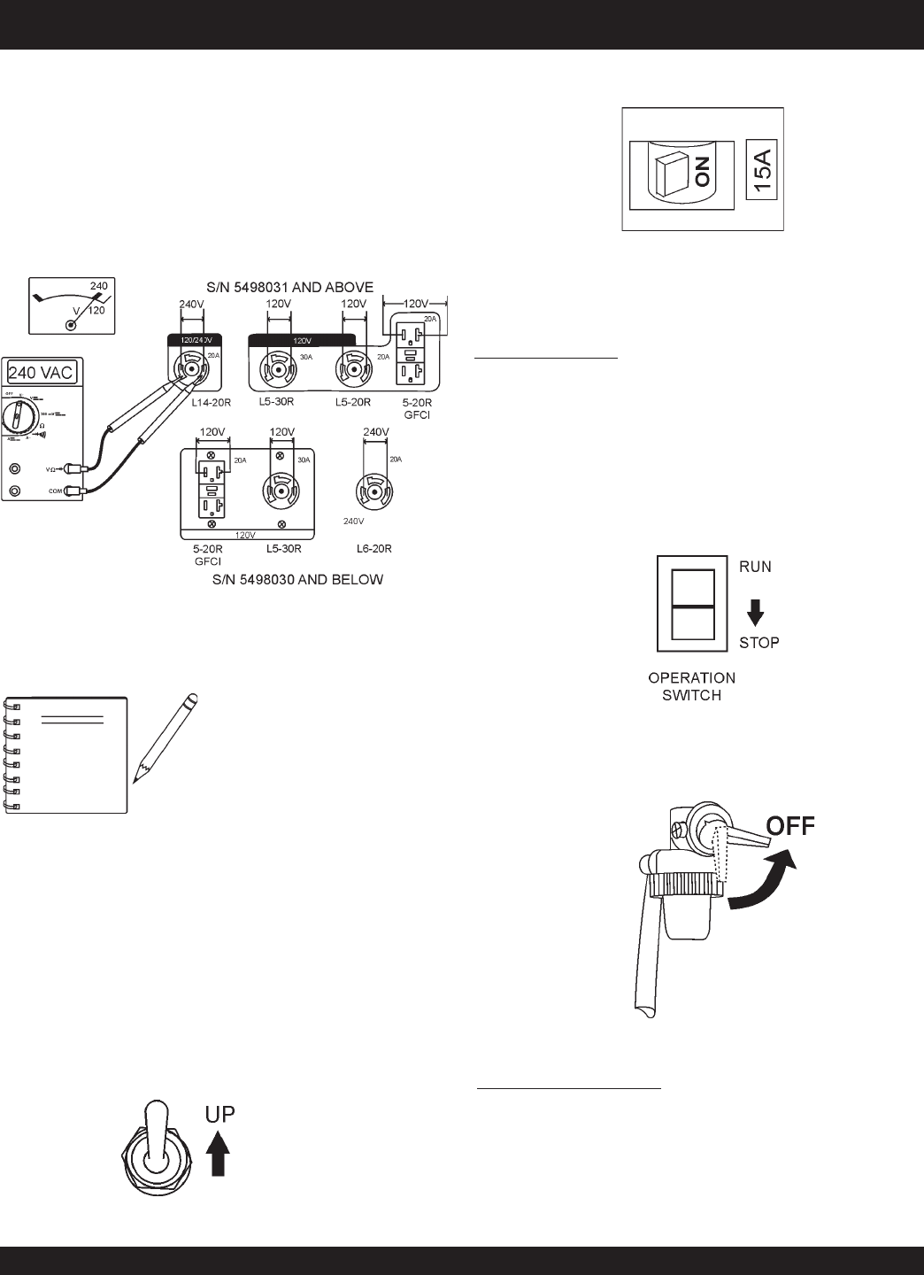
3. Place the
operation switch
(Figure 23) in the STOP
position.
4. Place the engine
fuel valve lever
(Figure 24) to the "OFF"
position.
”
Emergency Showdown
1. Place the
operation switch
(Figure 23) in the STOP
position.
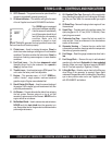
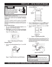
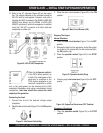
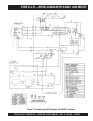
13. Refer to the AC voltmeter (Figure 20) on the control
box. The voltage indicated on the voltmeter should be
240 VAC with no load applied. If desired, verify with a
voltmeter that 240V is present at the NEMA L6-20R (S/N
5498030 and below) and the NEMA L14-20R (S/N
5498031 and above) twist-lock receptacles. In addition
verify that 120 VAC is present at all other twist-lock
receptacles on either unit.
Figure 20. 240/120 VAC Receptacles
NOTE
When the
full power switch
is
in the 240V (down) position, up
to half of the rated power of the
generator is available at the
120V duplex receptacle or any
twist-lock receptacle on either
unit; or full rated power can be obtained at the 240V
receptacle. Rembmber, when using a combination of dual
receptacles,
total load should not exceed the rated
capacity of the generator.
Connecting the Load
1. Connect the load to the desired voltage output
receptacle.
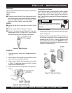
2. Place the idle control switch (Figure 21) in the ON position
(Up).
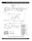
3. Place the main circuit breaker (Figure 22) in the ON
position.
Figure 21. Idle Control Switch (Up)
Figure 22. Main Circuit Breaker (ON)
Figure 23. Operation Switch (Stop)
Figure 24. Engine Fuel Valve Lever (OFF Position)