


STOW G-4.5R A.C. GENERATOR — OPERATION & PARTS MANUAL — REV. #3 (03/13/06) — PAGE 19
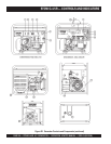
STOW G-4.5R — CONTROLS AND INDICATORS
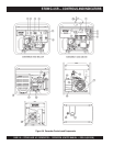
1. Idle Control Switch – This unit is provided with an
automatic idle control for noise suppression and reduced
fuel consumption. The automatic idle control automatically
engages under a no-load condition. With the automatic
idle control switched “ON”, the engine revolutions will
automatically drop to about 2600 rpm (low-speed
operation) within 3 seconds after the load stops. When the
operation is resumed, the engine speed is automatically
increased to about 3600 rpm (high-speed operation) as
soon as the load is connected.
2. Operation Switch – Place this
rocker
switch in the "RUN"
position (up) for normal operation. To turn-off the generator
place this switch in the "STOP" position (down).
3. Main Circuit Breaker – This 2-pole 15 amp breaker
protects the generator from short circuiting or overloading.
When starting the generator
always
have the circuit breaker
placed in the "OFF" position.
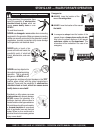
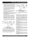
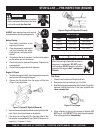
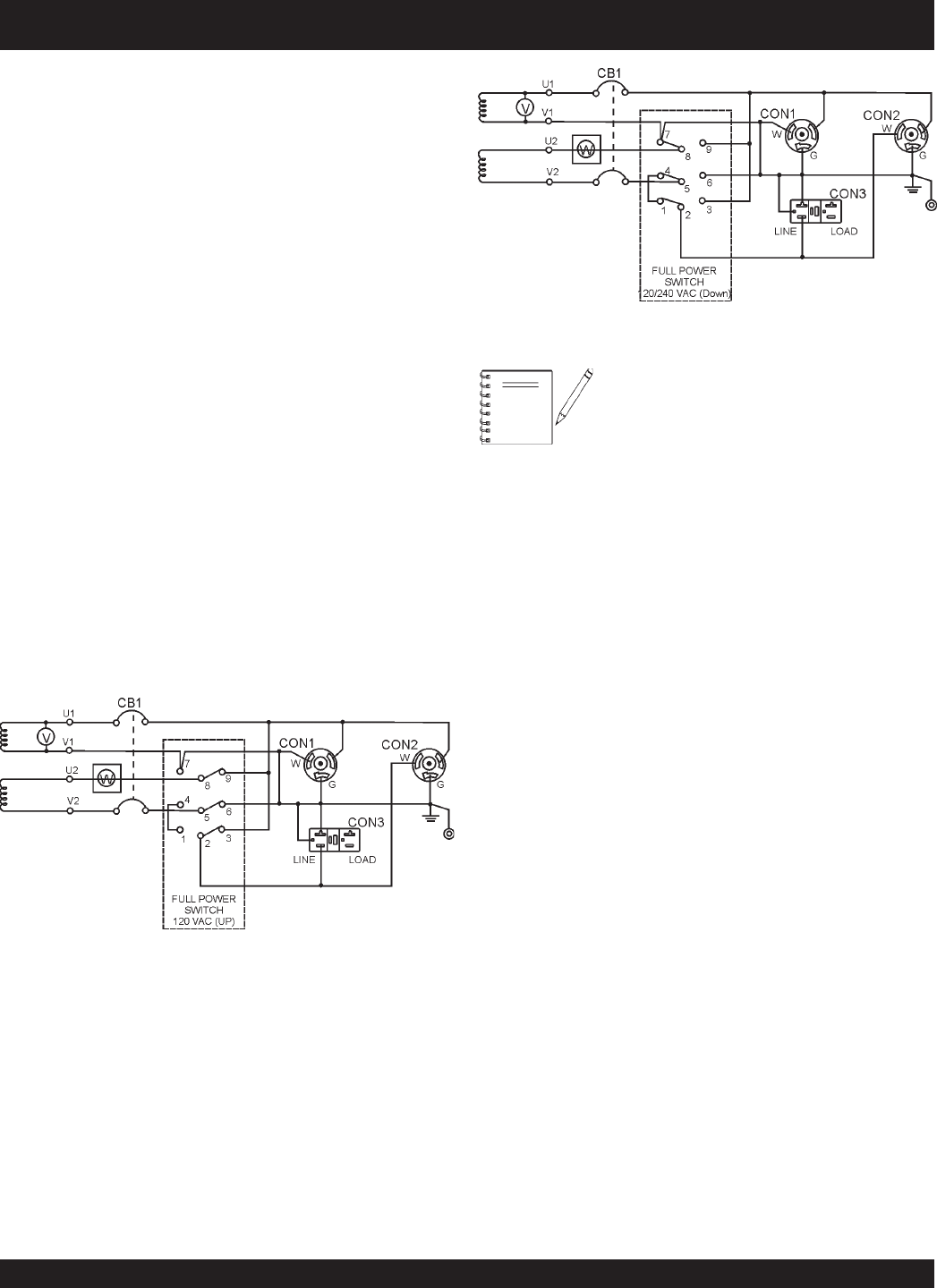
4. Full Power Switch – This generator is provided with a full
power switch. Figures 3B and 3C show simplified wiring
diagrams of the dual voltage system. When the full power
switch is in the 120 volt (up) position, you can take up
full
rated power
of the generator at 120 volts from the GFCI
duplex receptacle, 120 volts at the 120 volt twist-lock
receptacle, or a combination of both receptacles as long
as the total load does not exceed the generator's capacity.
When the full power switch is in the 240 volt (down) position,
you can take up to half of the rated power of the generator
at 120 volts from the GFCI receptacle and up to half of the
rated power of the generator at 120 volts from the twist-lock
120 volt receptacle; or full rated power of the generator at
240 volts from the twist-lock 240 volt receptacle.
Figure 3B. Full Power Switch 120VAC (Up)
Simplified Wiring Diagram
Figure 3C. Full Power Switch 120/240 VAC (Down)
Simplified Wiring Diagram
5. AC-Voltmeter – This voltmeter indicates (with a mark) the
rated 60 Hz, single phase output voltage. In addition the
voltmeter can also be used as a diagnostic tool. If the
voltmeter indicator (needle) is below the rated voltage,
engine problems may exist (low/high RPM's). To prevent
damage to the generator or power tools turn the generator
OFF and consult your authorized STOW service dealer.
6. 240 VAC Receptacle, 20 Amps – This receptacle will
provide 240V when the full power switch is placed in the
240/120 volt position (down). Applies to units with S/N
5498030 and below.
7. 120 VAC Receptacle, 30 Amps – This receptacle will
provide 120V when the full power switch is placed in either
the 120 or 240 volt position. Applies to units with S/N
5498030 and below.
8. GFCI Receptacle, 20 Amps – This receptacle will provide
120V at all times no matter the position of the full power
switch. Applies to all units.
9. 120 VAC Receptacle, 30 Amps – This receptacle will
provide 120V when the full power switch is placed in either
the 120 or 240 volt position. Applies to units with S/N
5498031 and above.
10. 120 VAC Receptacle, 20 Amps – This receptacle will
provide 120V when the full power switch is placed in either
the 120 or 240 volt position. Applies to units with S/N
5498031 and above.
11. 240 VAC Receptacle, 20 Amps – This receptacle will
provide 240V when the full power switch is placed in the
240/120 volt position (down). Applies to units with S/N
5498031 and above
When the full
power switch
is in the 120
volt position, the 240V receptacle cannot
be used.
NOTE