


PAGE 28 — STOW G-4.5R A.C. GENERATOR— OPERATION & PARTS MANUAL — REV. #3 (03/13/06)
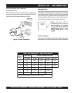
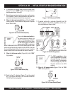
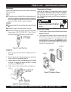
6. If the engine has started, slowly return the choke lever
(Figure 12 ) to the
“OPEN”
position. If the engine has not
started repeat steps 1 through 6.
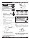
7. Before the generator is placed into operation, run the engine
for 3-5 minutes. Check for abnormal smells, fuel leaks, and
noises that would associate with lose components.
8.
Place
the
idle control switch
(Figure 15) in the "OFF"
(down) position. This will allow the engine run at speed
about 3600 RPM's
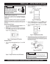
Figure 17. AC Voltmeter (120VAC)
Figure 15. Idle Control Switch (Down)
Figure 16. Full Power Switch (Up)
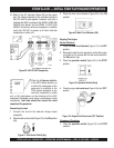
11. If desired, verify with a voltmeter (Figure18) that 120
VAC is present at the GFCI receptacle and the twis-
lock receptacles as shown below.
9.
Place
the
full power switch
(Figure 16) in the "120V"
(Up) position.
Figure 18. 120 VAC Receptacles
NOTE
The
240V receptacle on either
unit
is not operational (no voltage)
when the full power switch is in
the 120V position. This receptacle
is active (voltage) only when the
full power switch is in the 240V
position.
NOTE
Placing the
idle control switch
in
the down position allows the
engine to operate at a maximum
speed of about 3600 RPM's. When
the idle control switch is place in
the up position (ON), the generator
will run at idle speed (2200 RPM's) until a load is applied, at that
time the engine speed will increase to 3600 RPM's as long as
the load is being applied. When the load is not in use, the engine
speed will drop back to the idle mode after about 3 seconds.
10. Refer to the AC voltmeter (Figure 17) on the control
box. The voltage indicated on the voltmeter should be
120 VAC with no load applied.
12.
Place
the
full power switch (
Figure 19) in the "240/
120V" (Down) position.
Figure 19. Full Power Switch (Down)
STOW G-4.5R — INITIAL START-UP ENGINE/OPERATION