


16 ► HP TWIN8 User Manual
GENERAL
Tests and adjustments should be performed
periodically to ensure the power unit is operating
at maximum efciency. Use a calibrated ow and
pressure tester. This tester can be used to isolate
problems in both the engine and hydraulic system prior
to any power unit disassembly.
TESTING THE HYDRAULIC CIRCUIT
The following tests can be performed to ensure that
the hydraulic pump is supplying the correct ow and
pressure and that the system relief valve is operating
properly.
During these tests, make sure the engine is warm and
operating smoothly. If test results are not as specied,
refer to the troubleshooting table in this section for
possible causes.
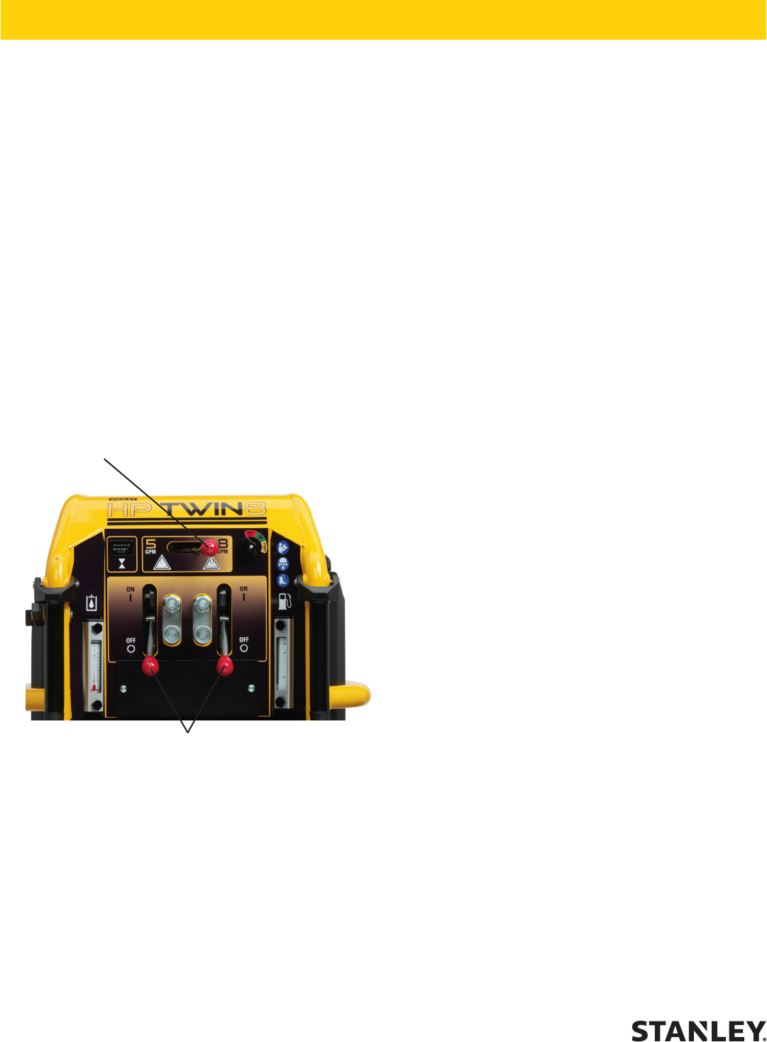
TESTING THE 5 OR 8 GPM CIRCUIT
To test the circuit, proceed as follows:
1. Install a calibrated ow and pressure tester across
the two hose ends (where the tool would normally
be connected).
2. Set both ow control levers to the OFF (down)
position.
3. Set the throttle control lever to the far left for 5
GPM, after the engine is started you can leave the
lever in this position if you are testing the 5 GPM
circuit or move the lever to the far right to test the 8
GPM circuit.
4. Check that the tester restrictor valve is fully open
(counterclockwise) on the ow and pressure tester.
5. Start the engine and allow it to run until warm.
6. With the throttle control in the far left position, the
(5-GPM) circuit can be tested, or moving the lever
to the far right will allow testing the (8-GPM) circuit.
a. 5-GPM Range 4-6 gpm/15-23 lpm
b. 8-GPM Range 7-9 gpm/26.5-34 lpm
7. Slowly turn the restrictor valve clockwise while
watching the pressure gauge. The ow rate shown
above in step 6 should stay at the selected ow
range.
8. When the pressure reaches 2100–2200 psi/145–
152 bar, the relief valve should begin to open.
The pressure at which the relief valve just begins
to open is commonly referred to as the “cracking
pressure”. At the “cracking pressure,” the ow rate
should start to drop because the relief valve is
allowing uid to bypass to the hydraulic reservoir.
The “cracking pressure” is preset at the factory
and if it is not within the above range (2100-2200)
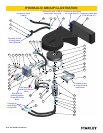
psi, the relief valve must be re-set as follows: The
relief valves are located on the control block which
is directly behind the couplers on the dash panel
(See item 10, pg-22) for location. Use a wrench to
loosen the nut on the relief valve.
9. Use an Allen wrench to adjust the relief valve.
Turn clockwise to raise the pressure and
counterclockwise to reduce the pressure. Tighten
the nut and retest.
10. Check both the 5 and 8 gallon ow settings and
then follow the same procedure to test the other
circuit (each circuit has its own relief valve).
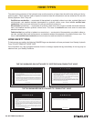
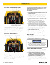
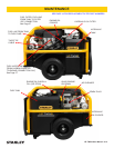
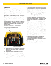
Flow Control Lever(s)
Throttle Control Lever
CIRCUIT TESTING