


GTR20 User Manual ◄ 17
GENERAL
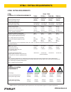
Tests and adjustments should be performed periodically
to ensure the power unit is operating at maximum ef-
ciency. Stanley Circuit Tester (part number 04182) is
recommended. This tester can be used to isolate prob-
lems in both the engine and hydraulic system prior to
any power unit disassembly.
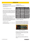
TESTING THE HYDRAULIC CIRCUIT
The following tests can be performed to ensure that the
hydraulic pump is supplying the correct ow and pres-
sure and that the system relief valve is operating prop-
erly.
During these tests, make sure the engine is warm and
operating smoothly. If test results are not as specied,
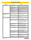
refer to the troubleshooting table in this section for pos-
sible causes.
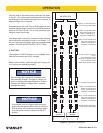
TESTING THE 5 GPM OR 10 GPM CIRCUIT
To test the circuit, proceed as follows:
1. Set the ow selector switches to the OFF (center) po-
sition.
2. Set the throttle control switch to AUTO-OFF position.
3. Connect the Stanley Circuit Tester across two hose
ends (where the tool would normally be connected).
4. Fully open the tester restrictor valve (counterclock-
wise).
5. Start the engine and allow it to run until warm.
6. Switch the ow selector switch to 5 or 10 gpm de-
pending on which ow you are testing.
7. With the engine at the programed speed, the test ow
gauge should read 4-6 gpm/15-23 lpm or 9-11 gpm/34-
41.6 lpm.
8. Slowly turn the restrictor valve clockwise while watch-
ing the pressure gauge. The ow rate should stay at 4-6
gpm/15-23 lpm or 9-11 gpm/34-41.6 lpm as the pressure
gauge reaches 2100-2200 psi/148-155 bar.
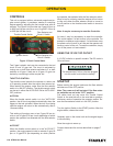
9. At 2100-2200 psi/148-155 bar, the relief valve should be-
gin to open. The pressure at which the relief valve just be-
gins to open is commonly referred to as the "cracking pres-
sure". At the "cracking pressure," the ow rate should start
to drop because the relief valve is allowing uid to bypass to
the hydraulic reservoir. The "cracking pressure" is preset at
the factory and if it is not within the above range, the relief
valve must be re-set as follows:
a. The relief valve is located on the right side of the unit just
behind the dash panel. It putrudes out from the manifold as-
sembly. Use a open end or box end wrench to loosen the nut
on the relief valve.
b. Use an Allen wrench to adjust the relief valve. Turn clock-
wise to raise the pressure and counterclockwise to reduce
the pressure.
c. Tighten the nut and retest.
TESTING & TROUBLESHOOTING