


17
30SS, 36SS, 45SS
Rev: 12/21/2011
Operating Instructions
Using your STANLEY Snow Blower
The following tips will help ensure proper and long lasting use of your STANLEY snow blower. ALWAYS wear proper
safety equipment when operating the snow-blower, and make sure you dress appropriately for cold weather.
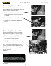
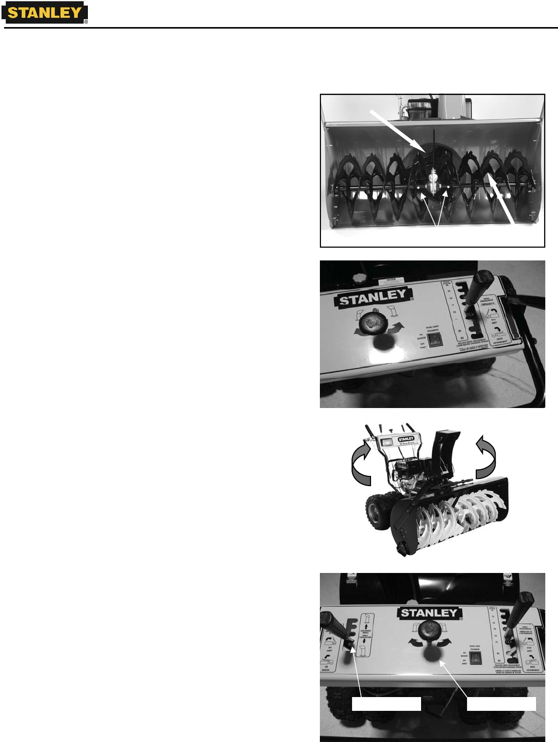
Figure 1
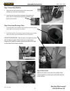
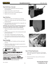
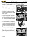
x Before use, always ensure there is nothing lodged in the auger,
or impeller area. Inspect the auger and impeller for damage
from rocks or other debris, and ensure there is no string, twine,
etc stuck on the auger or impeller shafts. Visually inspect for
loose hardware or any control cables that are loose or
disconnected. Ensure the shear-pins are intact before
operation.
x Inspect the area you will be operating the snow blower in.
Avoid areas with rocks, large branches and limbs, or other de-
bris that may damage the snow-blower. Only operate the snow
blower on paved ground.
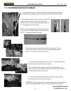
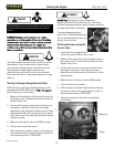
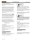
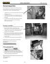
Figure 2
x To pro-long the life of the friction wheel system, do not par-
tially-engage the drive system, or continually engage and dis-
engage the drive system if the engine begins to slow under
heavy loads. When operating the snow-blower in dense wet
snow, or significant amounts of snow, use a slower speed on
the transmission.
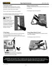
Figure 3
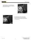
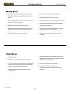
x The STANLEY Snow Blower uses a “live axle” which means the
wheels on either side of the snow blower turn together. When
turning the snow-blower 180
o
dis-engage the drive system.
Shift to Speed 1. Re-engage the drive handle and pull on the
control handle to shift the weight distribution to the outside
tire. This will assist in turning the snow blower, and is espe-
cially important for the 45SB which uses double tires on each
side.
Example: If turning left, shift the weight of the snow
blower to the right. If turning right, shift the weight of
Figure 4
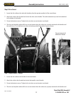
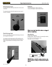
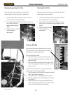
x Set the desired discharge direction and angle before engaging
the auger/impeller. Do not adjust the discharge direction or
angle while throwing snow. The extra forces may damage the
cables.
Shear-Pins
Auger
Impeller
Figure 1
Figure 3
Figure 4
Discharge Angle Chute Direction
Figure 2