


12 www.ferrisindustries.com
Installation
A
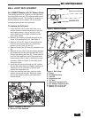
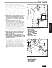
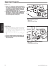
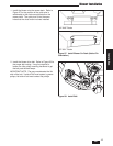
Figure 16. Mower PTO Belt
A. Idler Arm
B. Stationary Idler Pulley
B
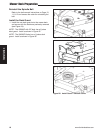
Remove the Spindle Belt
IS500Z & IS1500Z Series:
1. Using a 1/2” breaker bar, place the square end in the
square hole located in the end of the idler arm (A,
Figures 16). Carefully rotate the breaker bar
clockwise, which will relieve the tension on the belt
exerted from the idler arm.
2. Slide the drive belt over the edge of the stationary
idler pulley (B). Carefully release the tension on the
breaker bar. Remove the belt from the right-hand
(discharge side) spindle pulley.
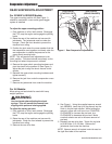
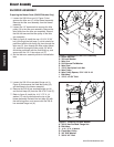
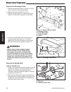
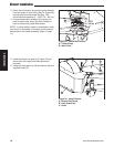
Remove the Discharge Chute
1. Remove the discharge chute (A, Figure 14), chute
mount rod (B) and mounting hardware.
2. Remove the chute lock bolt (C) and nut.
3. Remove the deck guard (D). Save the bolts and
washers, as they will be required in a later step.
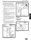
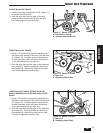
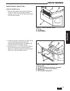
1-1/2"
(3,8 cm)
5/8"
(1,6 cm)
3/8" Drill
Figure 14. Remove Chute & Guard
A. Discharge Chute
B. Chute Mount Rod
C. Chute Lock Bolt
D. Guard
A
B
D
C
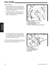
4. Examine the discharge chute mount bracket on
the mower deck (see Figure 15). If the hole
pattern looks like the one shown, you must drill a
3/8” hole in the location specified in Figure 15.
Figure 15. Discharge Chute Mount
WARNING
IS500Z, 1000Z, IS1500Z, IS2000Z, IS3000Z,
IS3100Z, IS4500Z, S150X & S200X Models:
Use extreme caution when rotating the idler
arm with the breaker bar, due to the increased
tension in the spring as the idler arm is being
rotated. Injury may result if the breaker bar is
prematurely released while the spring is under
tension.
Mower Deck Preparation