


16
Section 4 - REPAIR & ADJUSTMENTS
WARNING
DO NOT attempt any adjustments, maintenance or
service with the engine or blade running. STOP
blade. STOP engine. Remove spark plug wire from
spark plug and secure wire away from spark plug.
Engine and components can be extremely hot. Avoid
burns by allowing engine and components sufficient
time to cool.
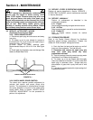
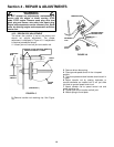
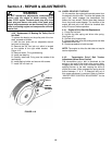
4.3.6. Replacement Of Bearing On Pulley End Of
Hex Shaft
To replace the bearing on the pulley end of the hex
shaft, proceed as follows:
1. Hold the hex shaft with an adjustable wrench
held next to the pulley.
2. Remove the 3/8” hex lock nut, which is located
on the outside of the right wheel bracket. See
Figure 4.10.
3. Remove holder, O-ring and bearing.
4. Install new bearing.
5. Carefully install new O-ring over the outside of the
new bearing.
6. Install bearing holder and secure with screws.
7. Install 3/8” hex lock nut.
FIGURE 4.10
4.4. WHEEL DRIVE BELT SERVICE
On this machine, the engine belt transmits power from
the engine to the drive disc. The drive disc powers the
poly-v belt, which engages the transmission that
powers the rear wheels. Should these belts become
worn, they could cause slippage. The condition of the
engine belt and poly-v belt should be checked after
every 25 hours of mower operation.
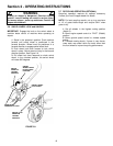
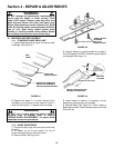
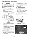
4.4.1. Engine to Drive Disc Belt Replacement
1. Empty the fuel tank.
2. Unhook the idler spring and driven disc spring.
See Figure 4.7.
3. Roll belt off of engine pulley
4. Remove belt from drive disc pulley groove and slide
underneath driven disc
5. Reverse procedure to install new belt.
NOTE: The engine to drive disc belt does not require
tension adjustment.
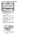
4.4.2. Transmission Poly-V Belt Tension
Adjustment (Wheel Drive Control)
The transmission poly-v belt is tensioned by the
spring on the end of the wheel drive control cable.
Engaging the wheel drive control extends the spring
applying tension to the belt, causing the drive to
propel the mower. When engaged the spring should
extend between ½” & ¾”. If extension falls out of
this range adjustment is required. Refer to Section
“WHEEL DRIVE CONTROL ADJUSTMENT” for the
procedure.
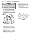
REMOVE
BOLTS
REMOVE
BEARING
RETAINER