


8
SECTION 3 - OPERATING INSTRUCTIONS
The operator must be familiar with the contents of this
manual before attempting to attach or operate this
mower. There may be specific operating and safety
instructions with the tractor that are not covered in this
manual. Read and follow the Instructions and Warnings
in the tractor manual before operating mower.
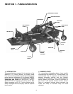
2.1 MOWER PREPARATION
Read and follow mower set up instructions and
inspect mower to insure mower has been
properly set up.
2.1.1. Check guards, shields, covers and
deflectors to make sure all are in place, securely
tightened and functioning properly.
2.1.2. Check lubrication points and gear box
fluid level for proper lubrication.
2.1.3. Inspect driveline. Driveline must be
securely attached to the mower gear box. All
driveline shields must be in place and rotate
freely.
2.1.4. Inspect mower blades for damage and
wear. Replace damaged or worn blades before
operating.
2.1.5. Verify that the discharge deflector is
attached and in the down/closed operating
position.
2.2 TRACTOR PREPARATION
The following are general guidelines.
Refer to the tractor manual or the tractor
manufacturer for specific instructions about the
preparation and operation of the tractor.
WARNING
The tractor may require counter weights and the
addition of an Operator Protective Structure when this
mower is attached. Follow the Safety Instructions
provided by the tractor manufacturer.
2.2.1. Remove tractor drawbar, if necessary, to
prevent interference and damage to the driveline.
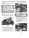
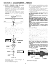
2.3 ATTACHING MOWER TO TRACTOR
This mower is designed to attach to a tractor
equipped with a standard Category 1 three (3)
point hitch and 540 rpm Power Take Off (PTO).
2.3.1. Place tractor and mower on level surface.
Lower tractor 3 point hitch.
2.3.2. STOP tractor. STOP engine. Set parking
brake. REMOVE key.
WARNING
DO NOT get between the tractor and mower when
the engine is running. STOP tractor. STOP engine.
Set Brake. REMOVE key. Allow all moving parts to
stop before leaving the operators position.
2.3.3. Attach lower tractor hitch arms to the pins
on the mower pivoting hitch. Secure with Lynch
pins.
2.3.4. Attach the top hitch link to the top hitch
link on the mower. Adjust the length of the link
and insert the pin. Secure pin with Lynch pin.
Tighten locking device on top hitch link.
2.3.5. Adjust stabilizer bars on lower hitch arms.
Refer to tractor manual for proper adjustment
procedure.
2.3.6. Attach driveline to tractor Power Take Off
(PTO). Twist coupling ring and slide driveline onto
tractor PTO shaft. Tug aggressively on driveline
yoke and insure that it is securely locked into
position.
WARNING
Tractor Power Take Off (PTO) shield must be in place
before operating mower. Driveline must be securely
locked to tractor and mower to prevent dangerous
disconnect condition.
2.3.7. Verify the minimum and maximum
working lengths of the driveline. The telescoping
tubes must overlap at least 1/3 of the length while
in use. The driveline must not bottom out or
disengage during transport. Verify driveline length
before engaging Power Take Off (PTO).
WARNING
DO NOT attempt any adjustments, maintenance or
service to mower with engine running. STOP tractor.
STOP engine. Set Brake. REMOVE key. Allow all
moving parts to stop before approaching mower.
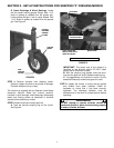
2.4 SETTING THE CUTTING HEIGHT.
2.4.1. Use tractor hitch to lift mower until all four
casters are off the ground.
2.4.2. STOP engine. Remove key. Make sure
all moving parts have stopped. Support mower
securely to prevent it from falling.
2.4.3. Adjust cutting height by moving the
spacers located on the mower casters. Placing
more spacers on the bottom will increase the
cutting height. Removing spacers from the bottom
will lower the cutting height. Each caster has a
total of 6 (1/2”) slotted spacers to adjust the
height of the deck. There must always be 6
spacers installed.
A. To remove spacers, first remove the Lynch
pin and washer from the top of the caster.
B. Raise cutting height by sliding spacer(s) off
of top and installing on bottom. Align slotted
end of spacer with the two flats on the caster
shaft. Slide spacer across flats. Repeat as
needed to raise height.