


32
Adjustments/Service
Service
NOTE: To assemble the auger housing to the frame,
have someone hold the auger clutch lever in the
ENGAGED position. This will move the idler arm
and pulley enough to allow the auger drive pulley
to move back into position.
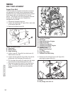
15.Assemble the auger housing (C, Figure 34) to the
frame with the four upper taptite screws (A) that
were removed in step 12. Tighten the two lower
taptite screws (B). Tighten all taptite screws to
40-50 lb-in (4,5-5,6 Nm).
16.Attach chute and offset tube previously removed
(Figure 32 and 33. Tighten all KEPS nuts to 11 lb-
ft (15 Nm).
17.Slide spout rotator rod (B, Figure 31) into worm
gear, and secure with hair pin (A).
18.Install rotator cover (A) and secure with 5/16-18
flange lock nut (B). Tighten nut to 11 lb-ft (15 Nm).
19.Install the auger drive belt (D, Figure 29) onto the
impeller pulley (H).
20.Slip the auger drive belt (D) under the idler pulley
(K).
21.Adjust the auger drive belt. See “Belt Adjustment:
Auger Drive Belt” in the Service section.
22.Adjust the belt guide. See “Belt Guide Adjustment”
in the Service section.
23.Install the belt cover (A, Figure 24). Tighten 1/4-20
screws (B) to 25-35 lb-in (2,8-3,9 Nm).
Note: Caution must be taken when tightening the
screws that secure the belt cover. Over tightening the
screws will deform the plastic.
24.Check the adjustment of the cables. See
“Adjustments - Auger Drive Adjustment and
Traction Drive Cable Adjustment” in the
Adjustment section.
25.Install the bottom panel (B, Figure 28). Tighten
1/4-20 screws to 25-35 lb-in (2,8-3,9 Nm).
26 Connect the spark plug wire.
Traction Drive Belt
If the snow thrower will not move forward, check the
traction drive belt for wear or damage. If the traction
drive belt is worn or damaged, replace the belt as
follows.
1. Disconnect the spark plug wire.
2. Remove the auger drive belt. See “Belt
Replacement” in the Service section.
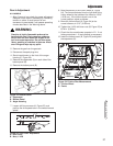
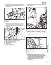
3. Remove the traction drive spring (E, Figure 29).
4. Remove the e-ring (J, Figure 29) from one end of
the swing plate axle rod (I).
5. Remove the swing plate axle rod (I) to allow the
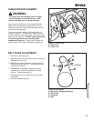
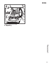
swing plate (A, Figure 35) to pivot forward.
6. Remove the old traction drive belt (A) from the
traction drive pulley (G) and from the traction drive
pulley (F). Replace the traction drive belt (A) with
an original factory replacement belt available from
an authorized Dealer.
7. Install the new traction drive belt (A) onto the
traction drive pulley (G) and onto traction drive
pulley (F).
8. Make sure the traction drive idler pulley (L) is
properly aligned with the traction drive belt (A).
9. Install the swing plate axle rod (I) and secure with
the e-ring (J) removed earlier.
10.The bottom of the swing plate (A, Figure 35) must
be positioned between the alignment tabs (B).
Make sure the swing plate is properly secured.
NOTE: If the drive will not engage after the traction
drive belt has been replaced, then check to make
sure that the swing plate is positioned between the
alignment tabs.
11.Attach the traction drive spring (E).
12.Install and adjust the auger drive belt. See Belt
Replacement in this section of the manual.
13.Adjust the belt guide. See Belt Guide Adjustment
in this section of the manual.
14.Install the bottom panel (B, Figure 28). Tighten
1/4-20 screws to 25-35 lb-in (2,8-3,9 Nm).
15.Install the belt cover (A, Figure 24). Tighten 1/4-20
screws (B) to 25-35 lb-in (2,8-3,9 Nm).
Note: Caution must be taken when tightening the
screws that secure the belt cover. Over tightening the
screws will deform the plastic.
16.Check the adjustment of the cables. See
Adjustments in this section of the manual.
17.Connect the spark plug wire.