


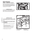

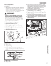
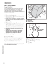
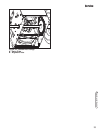

Figure 24. Friction Disc Measurement
A. Friction Wheel
B. Frame
4-5/16”
(10.95cm)
27
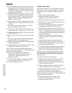
Adjustments/Service
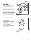
Run-In Adjustment
ALL MODELS
1. After 5 hours of use, check for proper adjustment.
Readjust clutch cable if necessary by increasing
tension on cable. A small amount of arm
movement is permissible if unit passes operating
checks described in the Warning above.
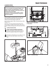
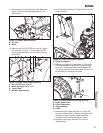
7. Loosen shift lever screws (A, Figure 23), and
position the shift speed lever in the lowest forward
speed.
WARNING
Gasoline is highly flammable and must be
handled with care. Drain gasoline outdoors.
Never drain the tank when the engine is still
hot from recent operation. Do not allow open
flame, smoking or matches in the area. Avoid
over-filling and wipe up any spills.
8. Note the position of the friction wheel (A, Figure
24). The correct distance from the right side of the
friction wheel to the outside of the frame is 4-5/16”
(10.95 cm). If the friction wheel is not in the
correct position, adjust as follows.
9. Move the friction wheel (A, Figure 24) to the
correct distance, 4-5/16” (10.95 cm).
10.Tighten the 1/4-20 shift lever nuts (B, Figure 23) to
60 lb-in. (6,8 Nm).
11.Check that the snowthrower operates in R1. If not
follow procedures 1-10 and readjust as necessary.
12.Install the bottom panel (B, Figure 22) and tighten
the capscrews (A).
Adjustments
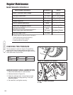
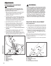
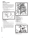
Figure 22. Bottom Cover
A. Capscrews
B. Bottom Panel
C. Auger Housing
C
2. Remove the gas from the gas tank.
3. Disconnect the spark plug wire.
4. Stand snowthrower on the front of the auger
housing (C, Figure 22).
5. Remove the capscrews (A) on each side of the
bottom panel (B).
6. Remove the bottom panel (B).
Figure 23. Shift Lever Adjustment
A. Shift Lever
B. Nuts, 1/4-20
A
B
B
A
A
A
B