


15
Operation
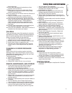
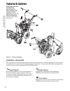
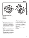
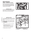
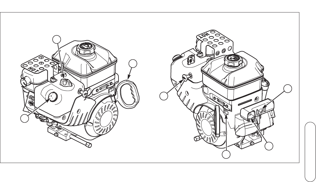
Figure 2. Engine Controls
A. Electric Start Button (Select Models)
B. Electric Start Connection (Select Models)
C. Stop Switch
D. Engine Key
E. Starter Handle
F. Primer Button
G. Choke Knob
Operation
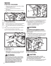
STARTING CONTROLS
See Figure 2 for the following instructions.
Electric Start
1. Electric Start Button - The Electric Start Button
(A) activates an electric starter mounted to the
engine, eliminating the need to pull the starter
handle. The Electric Start Button operates on AC
current, which is provided by connection (B) to the
extension cord provided with units equipped with
this feature.
Connect this extension cord ONLY
to a properly grounded 3 prong electrical
outlet.
Manual Start
2. Starter Handle - The starter handle (E) connects
to a starter cord to manually start the engine.
Pulling starter handle rapidly spins the engine
crankshaft, cycles the engine, and generates the
spark necessary for starting the engine.
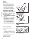
3. Primer Button - When pressed, the primer button
(F) provides initial fuel to help start a cold engine.
Normally, pressing the primer button twice will
provide enough fuel to start a cold engine.
A
F
G
B
D
E
C
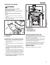
4. Engine Key - The engine key (D) prevents the
engine from being started by unauthorized
individuals. The key must be fully inserted into the
key slot for the unit to start. The key is also used to
stop the engine by pulling the key out of the key
slot.
5. Choke Knob - The choke knob (G) adjusts the
air/fuel mixture, and is used to help start a cold
engine by providing a richer mixture. Once the
engine is warm and running smoothly, the choke
knob should be set to the off position to provide a
normal air/fuel mix.
6. Stop Switch - Switch (C) to the ON position to
operate the engine. Switch to the OFF position to
stop the engine.