Not for
Reproduction
www.snapper.com20
Operation
WARNING
The mulching cover must remain on the machine at all
times. Do not remove.
!
!
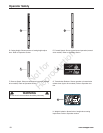
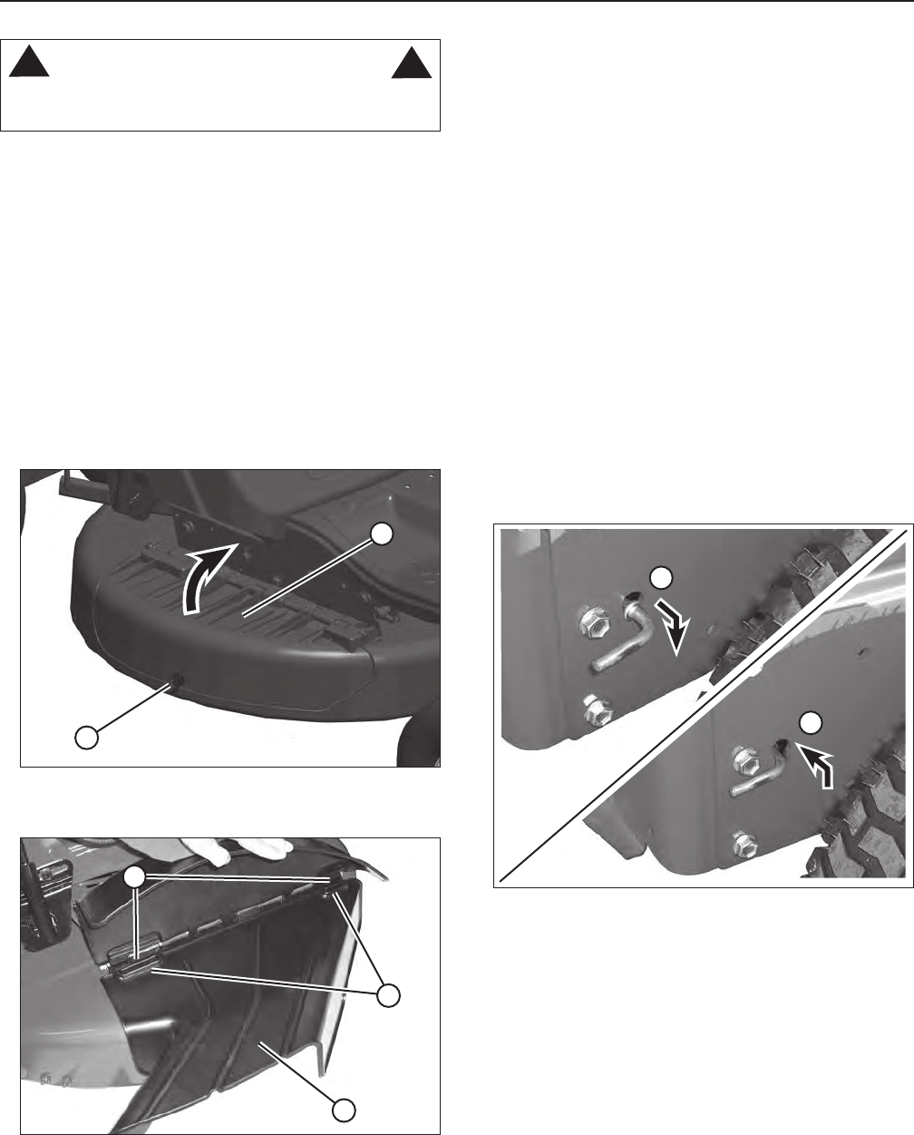
2. Raise the mulching cover. Replace the washer and
wing nut onto the retaining bolt in the deck, tightening
securely.
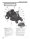
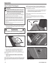
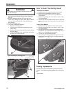
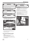
3. Install the discharge deflector (A, Figure 20) to the
mower deck, making sure that the slots (B) in the deflec-
tor fit over the locking tabs (C) on the mulching cover
hinge bracket.
4. Lower the mulching cover.
5. To remove the discharge deflector:
• Raise the mulching cover.
• Lift and remove the discharge deflector from the
mower deck.
• Remove the wing nut and washer from the retaining
bolt in the deck.
• Lower the mulching cover, securing with the washer
and wing nut. Tighten securely.
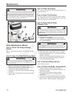
Figure 19: Raising the mulching cover
A
B
Figure 20: Installing the discharge deflector
B
C
A
How To Push The Unit By Hand
Manual Drive Models:
1. Make sure the unit is parked on a flat, even surface.
2. Make sure the transmission shift lever is in the
Neutral (N) position. Refer to “How To Engage the
Transmission”.
3. Release the parking brake, if set. Refer to “How To Set
The Parking Brake”.
4. The unit can now be pushed by hand. Be sure to set the
parking brake after the unit is moved to the desired loca-
tion.
Hydro Drive Models:
1. Make sure the unit is parked on a flat, even surface.
2. Release the parking brake, if set. Refer to “How To Set
The Parking Brake”.
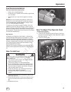
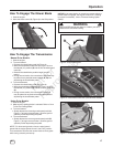
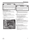
3. Move the transmission release lever (located behind
the right rear tire) out and down into the locking slot (A,
Figure 21) to disengage the transmission.
4. The unit can now be pushed by hand.
5. After moving the unit to the desired location, move the
transmission release lever up and in (B) to engage the
transmission.
Figure 21: Transmission release lever
A
B
Towing Implements
The maximum horizontal drawbar force allowed is 34 lbs
(150 N) *. The maximum vertical drawbar force is 20 lbs (90
N) *.
* Approximate


