


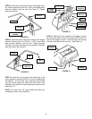
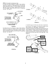


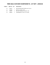

STEP 12: Assemble the discharge tubes:
a. Install one strap assembly to each of the locations
marked ‘A’ in Figure 19. Insert one #10-24 x 5/8” pan head
screw, fitted with one #10 x 1/2” OD flat washer, out through
the hole in the tube or adapter. Secure with one #10 x 3/4”
OD flat washer, strap, and #10-24 tee nut, tightening
securely. See Figure 17.
b. Install one tee nut assembly to each of the locations
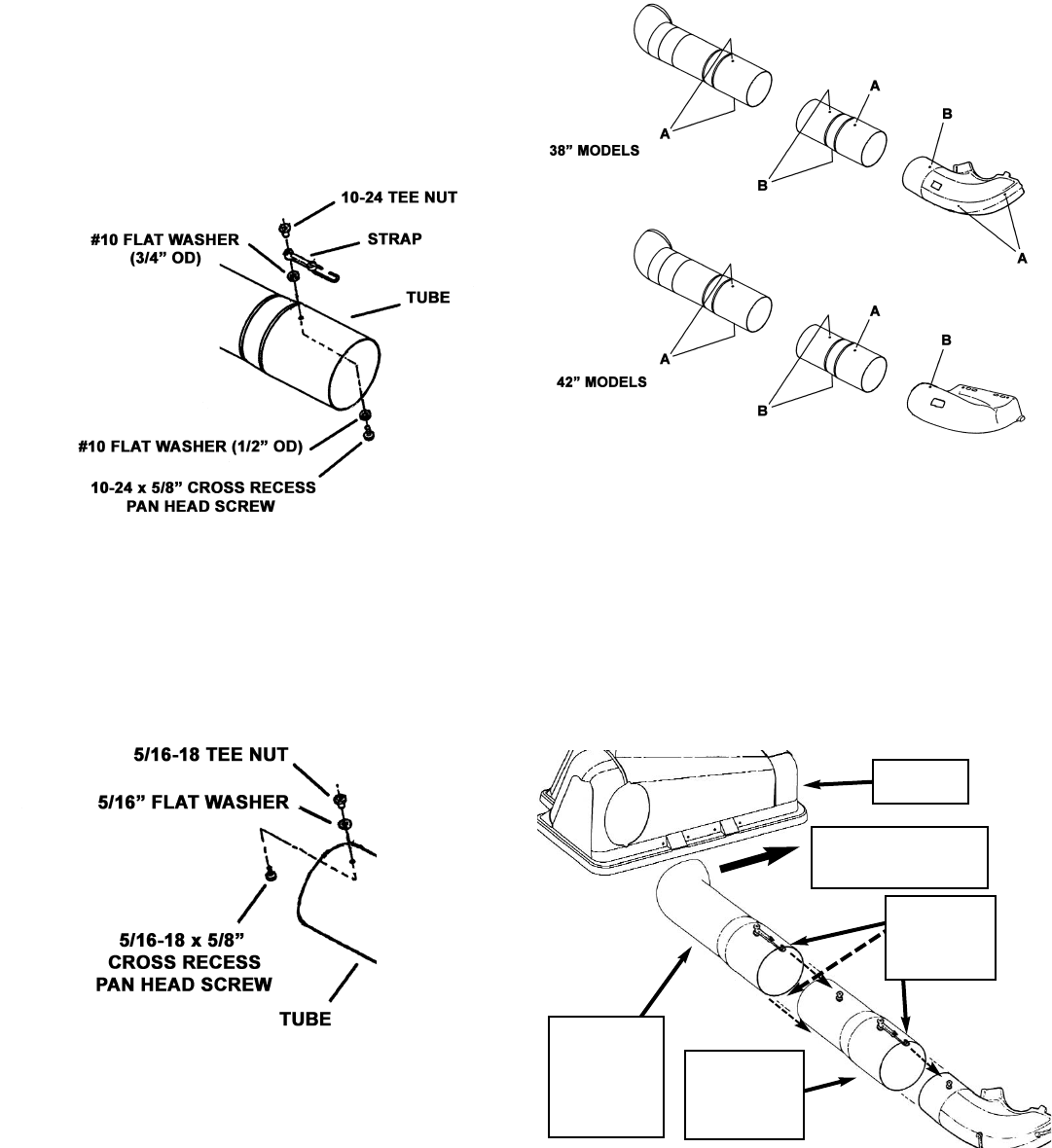
marked ‘B’ in Figure 19. Insert one 5/16 x 5/8” pan head
screw out through the hole in the tube or adapter. Secure
with one 5/16” flat washer and 5/16-18 tee nut, tightening
securely. See Figure 18.
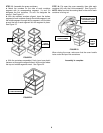
c. Install the large end of the lower tube (short, straight tube)
onto the end of the adapter, and secure the strap on the
tube to the tee nut on the adapter. See Figure 20.
d. Intall the curved end of the upper tube into the hole in the
cover assembly, making sure the discharge faces toward
the left of the unit. Install the bottom of the upper tube onto
the top of the lower tube, and secure the two straps on the
upper tube to the two tee nuts on the lower tube. See
Figure 20.
5
FIGURE 17
ATTACH TO ALL
‘A’ LOCATIONS
(SEE FIGURE 19)
FIGURE 18
ATTACH TO ALL
‘B’ LOCATIONS
(SEE FIGURE 19)
FIGURE 19
FIGURE 20
COVER
ASSEMBLY
INSTALL
UPPER TUBE
INTO COVER
ASSEMBLY,
THEN OVER
LOWER TUBE
DISCHARGE SHOULD
FACE TOWARD LEFT
SIDE OF UNIT
INSTALL
LOWER TUBE
OVER
ADAPTER
SECURE
STRAPS TO
‘T’ NUTS
(3 PLACES)