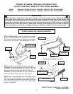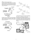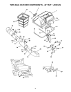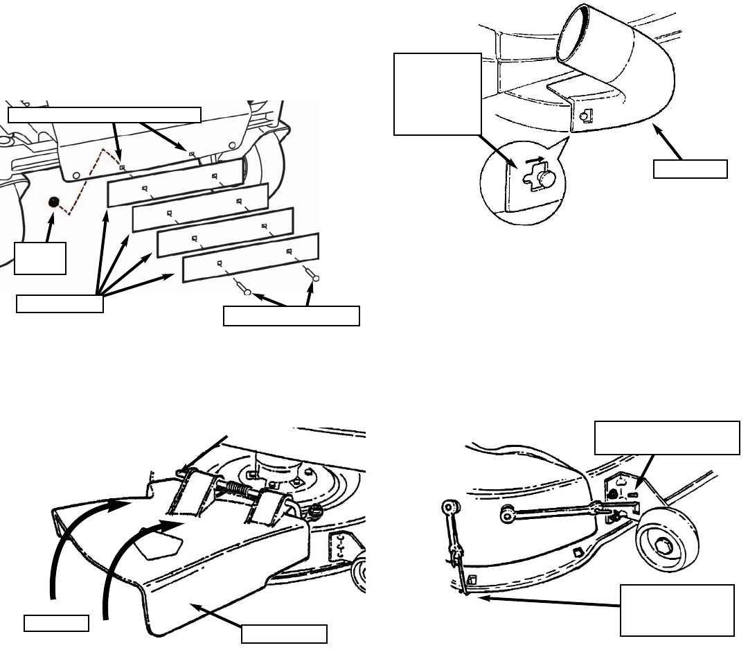
STEP 3: Remove the two innermost front carriage bolts
securing the unit footrest to the frame. Install the four
ballasts against the front of the machine, securing with the
supplied 5/16 x 1-3/4” carriage bolts and lock nuts in place
of those removed. Tighten hardware securely. See Figure 4.
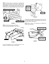
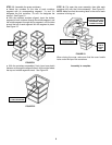
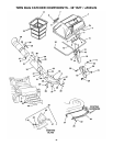
STEP 4: Install the bag adapter (38” Deck):
a. Raise the discharge deflector. See Figure 5.
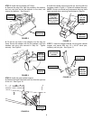
b. Use the existing tee nut for mounting the rear of the
adapter to the side of the deck. See Figure 6.
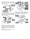
c. Secure the front adapter mounting strap to the slots in the
anti-scalp wheel bracket. Secure the other strap to the hole
in the deck flange. See Figure 7.
NOTE: Refer to Step 12 for instructions on installing the
adapter mounting straps.
FIGURE 4
REMOVE EXISTING HARDWARE
CARRIAGE BOLTS
BALLASTS (4)
FIGURE 5
DEFLECTOR
RAISE
FIGURE 6
ADAPTER
PLACE HOLE
OVER TEE NUT
AND SLIDE
ADAPTER
FORWARD
2
FIGURE 7
SECURE SECOND
STRAP TO HOLE IN
DECK FLANGE
SECURE FRONT STRAP
TO WHEEL BRACKET
LOCK
NUT (2)


