


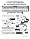
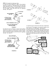


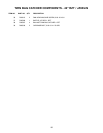

STEP 8: Install the U-tube onto the top of the bagger chan-
nel, securing with three 5/16-24 x 1-5/8” curved head bolts,
split lock washers, and hex nuts. See Figure 13. Tighten
hardware securely.
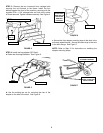
STEP 9: Install the center tube into the center of the bagger
channel, securing with two 5/16-24 x 1-5/8” curved head
bolts, split lock washers, and hex nuts. Tighten hardware
securely. Also insert one tube end cap into each of the three
open tube ends. See Figure 14.
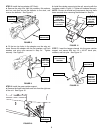
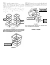
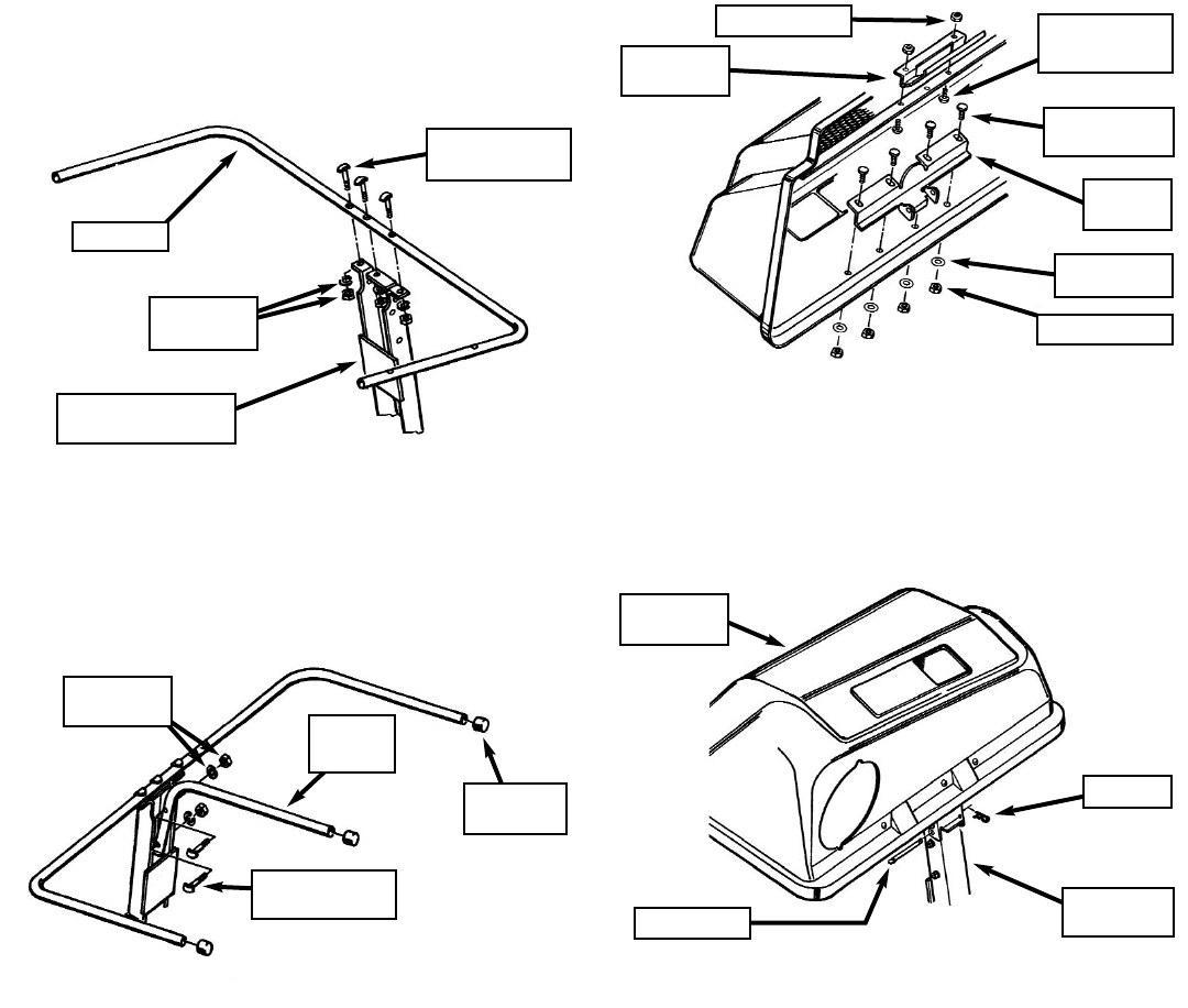
STEP 10: Install the cover hinge to the inside back of the
cover assembly, securing with four 1/4 x 3/4” carriage bolts,
flat washers, and lock nuts. Also, install the cover handle
onto the screen support bar, behind the front of the cover
assembly, securing with two pan head screws and lock nuts.
See Figure 15.
NOTE: On some units, the cover handle has been pre-
assembled onto the cover assembly.
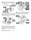
STEP 11: Attach the cover assembly to the bagger channel
by aligning the holes in the cover hinge with the top set of
holes in the bagger channel. Insert the hinge pin through
the holes, and secure with a hair pin. See Figure 16.
4
FIGURE 13
U-TUBE
BACK OF BAGGER
CHANNEL
CURVED HEAD
BOLT (3)
WASHER &
NUT (3)
FIGURE 14
CENTER
TUBE
CURVED HEAD
BOLT (2)
WASHER &
NUT (2)
TUBE END
CAP (3)
FIGURE 15
CARRIAGE
BOLT (4)
COVER
HANDLE
COVER
HINGE
LOCK NUT (2)
PAN HEAD
SCREW (2)
FIGURE 16
BAGGER
CHANNEL
COVER
ASSEMBLY
HAIR PIN
HINGE PIN
LOCK NUT (4)
FLAT
WASHER (4)