


33
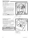
Regular Maintenance
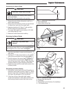
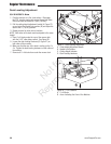
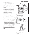
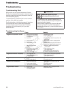
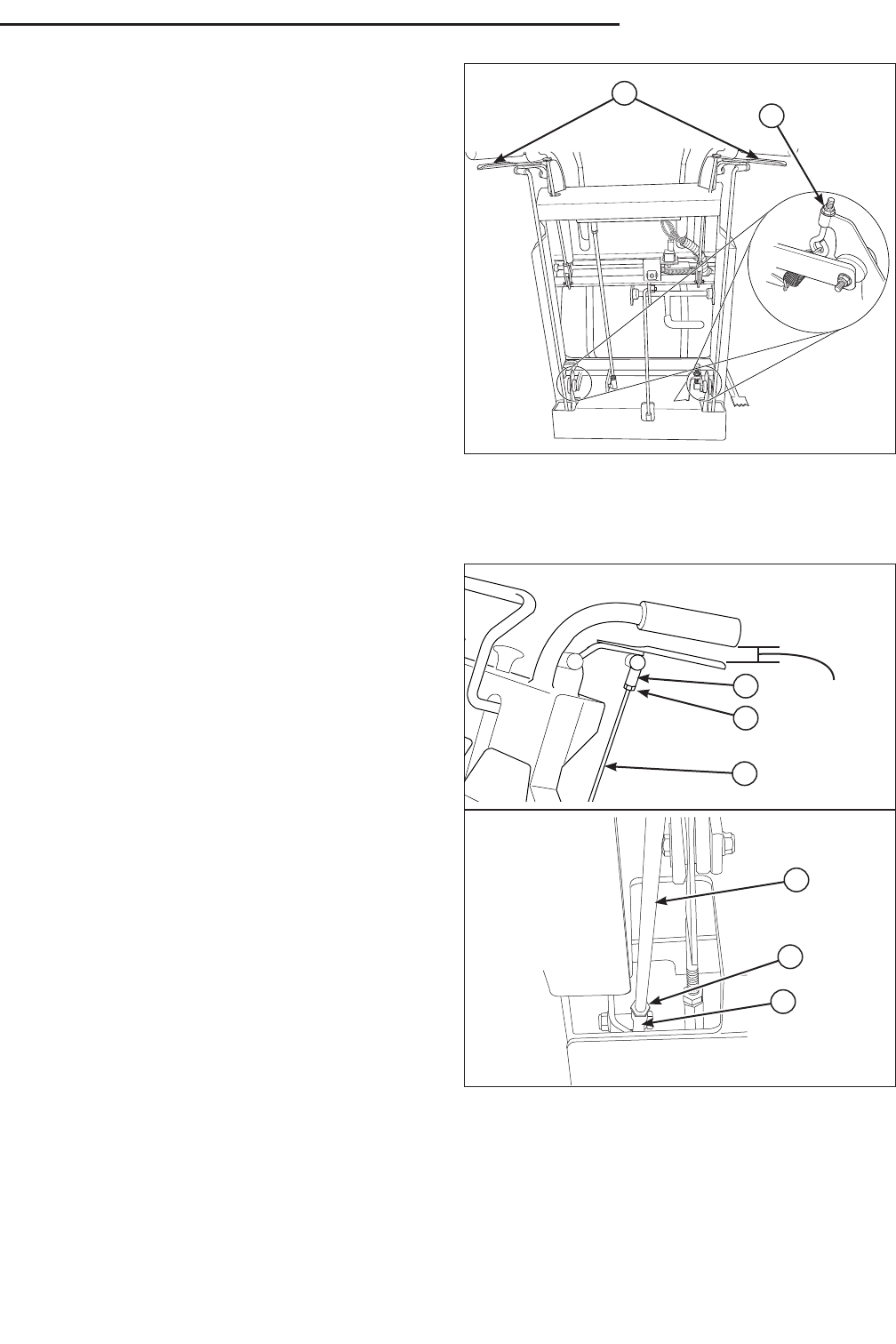
Figure 33. Reverse Speed Control Levers Comfort
Adjustment
A. Reverse Speed Control Levers
B. Lock Nut
Reverse Speed Control Levers
Comfort Adjustment (S/N: 2014522399 & Below)
The amount of pressure necessary to depress the Reverse
Speed Control Levers (A, Figure 33) can be adjusted to meet
the comfort needs of the operator.
1. Disengage the PTO, engage the parking brake and turn
off the engine.
2. To increase the amount of pressure necessary to
depress the Reverse Speed Control Levers turn the
lock nut (B) CLOCKWISE until the desired comfort
level is achieved. To decrease the amount of pressure
necessary to depress the Reverse Speed Control Levers
turn the lock nut COUNTER-CLOCKWISE until the
desired comfort level is achieved.
3. Repeat process for other side of the unit.
NOTE: Both Reverse Speed Control Levers should be
adjusted so that it takes the same amount of pressure to
depress both handles.
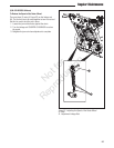
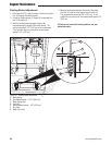
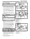
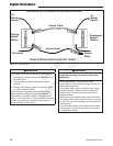
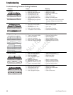
Handle Placement Adjustment (All Models)
There should be approximately 1” (2,54 cm) fo clearance
in between the handle bars and the reverse speed control
levers when the forward speed control lever is in the neutral
position.
To adjust:
1. Loosen the jam nuts (B, Figure 34) that are located on
the top and the bottom of the reversing linkage rod (A).
2. Adjust the linkage rod:
• To increase the amount of clearance between the
handle bars and the reverse speed control levers, turn
the linkage rod (A) clockwise.
• To decrease the amount of clearnace between the
handle bars and the reverse speed control levers, turn
the linkage rod counter-clockwise.
3. Once the measurement of 1” (2.54 cm) is achieved,
tighten the jam nuts against the linkage rod ball joints.
4. Repeat the process for the other side of the unit.
Both reverse speed control levers should be adjusted
equally.
A
B
1”
(2.54 cm)
A
Figure 34. Handle Placement Adjustment
A. Reversing Linkage Rod
B. Jam Nuts
C. Linkage Rod Ball Joints
C
B
A
B
C
Not for
Reproduction