


28
www.SnapperPro.com
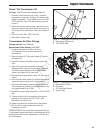
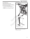
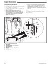
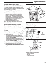
Figure 23. Parking Brake Adjustment
A. Brake Spring
B. First Measurement - 2-1/2” (6,35 cm)
C. Brake Spring Rod
D. Lock Nut
E. Second Measurement - 1/8” (0,32 cm)
F. Set Collar
G. Brake Pivot Link
A
Parking Brake Adjustment
1. Disengage the PTO, stop the engine, remove the ignition
key, and engage the parking brake.
2. Locate the brake springs (A, Figure 23) underneath the
rear of the machine.
3. With the parking brake engaged, measure the
compressed spring length of the brake spring. The
spring should be 2-1/2” (6,35 cm) when compressed.
If not, position the lock nut until the measurement
equals 2-1/2” (6,35 cm).
4. Measure the distance between the back of the brake
pivot link (G) and the front edge of the set collar (F).
The measurement should be 1/8” (0,32 cm). If not,
position the set collar until the measurement equals 1/8”
(0,32 cm).
If this does not correct the braking problem, see your
authorized dealer.
B
D
C
F
E
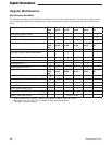
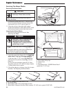
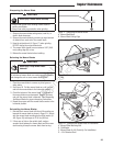
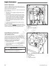
Regular Maintenance
G
Not for
Reproduction