


32
www.SnapperPro.com
Transmission Drive Belt Replacement
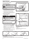
1. Park the unit on a smooth, level surface such as a
concrete floor. Disengage the PTO, engage the parking
brake, turn off the engine and remove the ignition key.
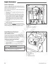
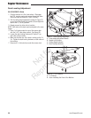
2. Loosen and remove the hardware that secures the
skid plate assembly (A, Figure 31) to the engine deck.
Remove the skid plate assembly from the engine deck.
3. Remove the PTO drive belt (see MOWER BELT
REPLACEMENT for removal instructions.)
4. Cut the wire tie that secures the PTO clutch wire harness
to the engine deck frame.
5. Unplug the PTO clutch wire harness from the PTO clutch
(B).
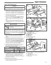
6. Loosen and remove the hardware that secures the PTO
clutch mounting tab (C) to the engine deck. Remove the
PTO clutch mounting tab.
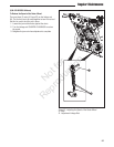
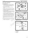
7. Loosen the nuts on the spring anchor eyebolt (G, Figure
32) to release the majority of the belt tension. Use
caution and remove the nut to completely release the
tension.
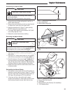
8. Remove the old belt and replace it with the new one.
Make sure that the V-side of the belt runs in the grooves
of the crankshaft pulley and transmission pulleys (B &
C).
9. Reinstall the spring anchor eyebolt (G) into the anchor
tab and loosely fasten the nut. Adjust the anchor eyebolt
until a coil-to-coil measurement of 4-7/8” (12,4 cm) is
achieved. Tighten the nut.
10. Using the hardware that was previously removed reinstall
the clutch anchor to the engine deck.
NOTE: Make sure that the slot in the PTO clutch lines up with
the PTO clutch mounting tab (C, Figure 31) underneath the
engine deck.
11. Reconnect the PTO clutch wire harness to the PTO
clutch.
12. Using a new wire tie secure the PTO clutch wire harness
to the frame and away from moving components.
13. Reinstall the PTO drive belt.
14. Using the hardware that was previously removed reinstall
the skid plates to the engine deck.
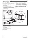
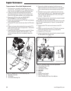
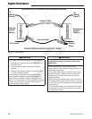
Figure 32. Hydraulic Pump Drive Belt Replacement
A. Transmission Drive Belt
B. Crankshaft Pulley
C. Transmission Pulleys
D. Idler Pulley
E. Idler Arm
F. Spring
G. Spring Anchor Eyebolt
H. Stationary Idler Pulley
I. Arrow Indicating the Front of the Machine
4-7/8”
(12,4 cm)
A
I
B
H
D
C
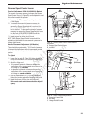
Figure 31. Remove the PTO Clutch Mounting Tab
A. Skid Plate Assembly
B. PTO Clutch
C. PTO Clutch Mounting Tab
A
C
H
E
F
G
B
C
Regular Maintenance
Not for
Reproduction