


22
www.snapper.com
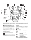
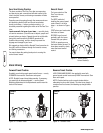
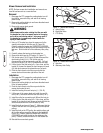
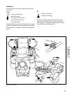
Figure 17. Mower Belt Routing
A. Arbor Pulleys
B. Back-Side Idlers
C. PTO Pulley
A
A
A
C
B
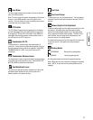
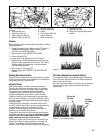
Figure 18. Release Belt Tension
A. Idler Arm
B. Stationary Idler Pulley
B
A
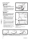
Mower Removal and Installation
NOTE: Perform mower deck installation and removal on a
hard flat surface such as a concrete floor.
Removal
1. Disengage the PTO, engage the parking brake, turn off
the ignition, remove the key, and wait for all moving
parts to stop.
2. Remove the cutting height pin and lower the attachment
lift to its lowest position.
3. Remove the mower deck guards.
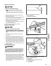
4. Using a 1/2” breaker bar, place the square end in the
square hole located in the idler arm (A, Figure 18).
Carefully rotate the breaker bar COUNTER-CLOCKWISE,
which will relieve the tension on the belt exerted from the
idler arm. Slide the belt off of the stationary idler pulley
(B).
5. Carefully release the tension on the breaker bar.
6. Remove the belt from the PTO pulley (C, Figure 17)
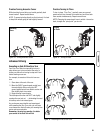
7. Pull the hair pins (C & D, Figure 19) and disconnect the
deck leveling links (I & J). Pull the hair pin and
disconnect the roller bar connecting rod (M). Pull and
turn the rod locks (A, B, E & F) to release the rod ends.
8. Lift the front of the deck using a 2 x 4 as a lever, pull the
handle (G) forward to release the front hangers rod ends
(H), then push rearward to release the rear rod ends.
9. Pivot the front wheels out of the way and slide the
mower deck out from under right side of the unit.
Installation
1. Disengage the PTO, engage the parking brake, turn off
the ignition, remove the key, and wait for all moving
parts to stop.
2. Remove the cutting height pin and lower the attachment
lift to its lowest position.
3. Pivot the front wheels out of the way and slide the
mower deck under the unit.
4. Install the leveling links and hair pins (I, J, C & D).
5. Lift the rear of the mower deck and install the rear lift
rods (K & L) and secure with the rear rod locks (E & F).
6. Install the roller bar connecting rod (M) and the hair pin.
7. Lift the front of the deck using a 2 x 4 as a lever, pull the
handle (G) to align the front hanger rod ends (H) with the
slots and secure with the front rod locks (A & B).
8. Install the belt as shown in Figure 17. Make sure that the
V-side of the belt runs in the pulley groves of the spindle
pulleys.
9. Install the belt on the PTO pulley, the spindle pulleys and
all the idler pulleys except the stationary idler pulley (B,
Figure 18). Carefully rotate the breaker bar COUNTER-
CLOCKWISE and install the belt on the stationary idler
pulley. Carefully release the tension on the breaker bar.
10. Reinstall the mower deck guards.
WARNING
Use extreme caution when rotating the idler arm with
the breaker bar, due to increased tension in the spring
as the idler arm is being rotated. Injury may result if
the breaker bar is prematurely released while the
spring is under tension.