


12
www.snapper.com
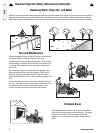
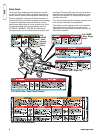
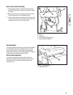
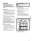
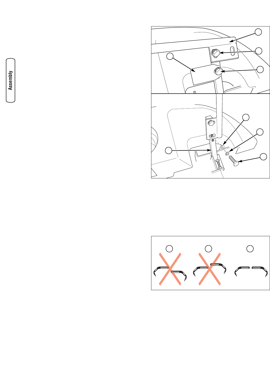
Figure 4. Lever Alignment & Placement Adjustment
A. Levers Misaligned (One Lever Tilted Behind the Other)
B. Levers Aligned Incorrectly (One Lever Tilted In Front of
the Other)
C. Levers Aligned Correctly
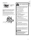
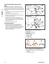
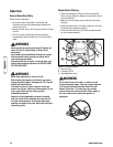
Figure 3. Install Control Levers (Left Side Shown)
A. Control Lever
B. Bottom Mounting Hardware
C. Manilla Tag
D. Upper Mounting Hardware
E. 5/16-18 x 1” Bolts
F. 5/16 Lock washers
G. 5/16 Washers
H. Control Lever Base
Install the Ground Speed / Steering Control
Levers
Positioning the Ground Speed / Steering Control Levers:
The ground speed / steering control levers (A, Figure 3) must
be moved to the upright position before attempting to operate
the machine.
1. Remove the bottom mounting hardware (B). Discard the
manilla tag (C).
2. Loosen the upper mounting hardware (D).
3. Position the ground speed / steering control levers in the
upright position. See Figure 3.
4. Loosely install the 5/16-18 X 1” bolt (E), 5/16” lock
washer (F), and 5/16” flat washer (G) through the ground
speed / steering control lever into the control lever base
(H) as shown in Figure 3.
5. Repeat process for other side of unit.
Lever Alignment Adjustment:
1. From the neutral position, pivot the ground speed /
steering control levers in towards the center of the
machine. If one of the levers is tilted further forward (B,
Figure 4) or back (A) then the other lever, pivot the levers
forward or backwards to align with each other (C).
Tighten the mounting bolts.
E
A B C
Shipping Position
Upright Position
A
D
B
C
F
G
H