


35
Troubleshooting, Adjustment, & Service
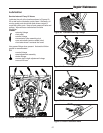
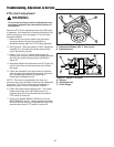
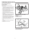
Steering Wheel Adjustment
NOTE: The steering wheel on Snapper models is not
adjustable.
1. Use a suitable punch to remove the roll pin at the
base of the steering wheel (B, Figure 31).
2. Pull down on the rubber boot to expose the two holes
in the steering shaft (A).
3. Align the hole in the steering wheel with the
appropriate steering shaft hole and install the roll pin.
NOTE: Steering wheel is factory installed with the roll pin
in the bottom hole.
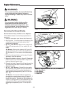
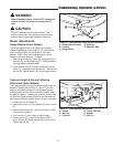
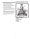
Steering Gear Adjustment
If there is excessive slack in the steering system, the
steering gear backlash can be removed.
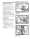
1. See Figure 32. Locate the steering gear assembly on
the underside of the tractor. Loosen the two nuts and
adjust the bracket so the gear teeth are closely
meshed.
2. Tighten nuts (A, Figure 32) to 36-44 ft. lbs. (49-59
Nm) after adjustment.
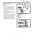
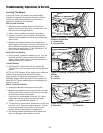
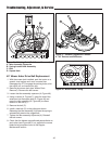
Brake Adjustment
1. Disengage the PTO, stop the engine, block the
wheels, remove the ignition key, and engage the
parking brake.
2. Remove the mower deck (see Mower Deck
Removal).
3. Locate the brake spring (A, Figure 33) and
adjustment nut (B).
4. With the parking brake engaged, measure the
compressed spring length. The spring should be 2-
1/2” (6,4 cm) when compressed.
If the spring is not within this range, turn the
adjustment nut (B, Figure 33) to compress or release
the spring.
If this adjustment does not correct a braking problem,
see your dealer.
Figure 32. Steering Gear Adjustment
A. Nuts
Figure 33. Brake Spring Adjustment
A. Brake Spring
B. Adjustment Nut
A
B
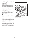
Figure 31. Steering Wheel Components
A. Steering Shaft
B. Roll Pin
C. Steering Wheel
B
A
C
Thicker Spoke
Faces Seat
A