


26
Regular Maintenance
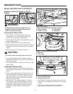
Battery Maintenance
Cleaning the Battery and Cables
Service Interval: Every 100 Hours
1. Disconnect the cables from the battery, negative
cable first (A, Figure 17).
2. Remove the battery hold-down (C) and battery.
3. Clean the battery compartment with a solution of
baking soda and water.
4. Clean the battery terminals and cable ends with a
wire brush and battery terminal cleaner until shiny.
5. Reinstall the battery in the battery compartment, and
secure with the battery hold-down (C).
6. Reattach the battery cables, positive cable first (B).
7. Coat the cable ends and battery terminals with
petroleum jelly or non-conducting grease.
WARNING
When removing or installing battery cables,
disconnect the negative cable FIRST and reconnect
it LAST. If not done in this order, the positive
terminal can be shorted to the frame by a tool.
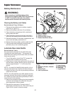
Figure 17. Battery
A. Negative Cable
B. Positive Cable & Cover
C. Rubber Hold-Down Strap
A
C
B
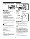
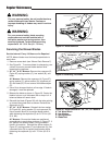
Lubricate Rear Axle Shafts
Service Interval: Yearly
We recommend removing the rear wheel hubs and
lubricating the axle shafts yearly. This prevents the
wheel hubs from seizing onto the axle shaft and makes
future service easier.
1. Turn off the ignition, turn off the PTO, engage the
parking brake, and block the front tires.
2. Using a jack or chain hoist positioned at the center of
the rear frame, carefully jack the unit up until the rear
tires are approximately 1" - 2" (2.5-5cm) off the
ground.
NOTE: For overall unit stability during service, do not
jack rear end higher than required for wheel removal.
3. Support the rear of the unit on jackstands positioned
under the rear frame.
NOTE: Your axle assembly may differ slightly from the
assembly pictured: the quantity of washers is adjusted
on a tractor by tractor basis during assembly to allow a
small amount of axle end-play.
4. Remove the hardware retaining the wheel assembly
to the axle and lubricate the axle shaft using anti-
seize compound or lithium grease.
5. Reinstall the components in reverse order of
disassembly and lower the unit. Be sure the key (A,
Figure 18) is in place in the axle keyway.
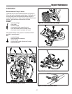
Figure 18. Rear Axle Hardware
A. Key F. Small Washer
B. Stationary Washer / Washer G. Retaining Ring
C. Spacer H. Axle Cap
D. Wheel & Hub I. Large Washer
E. Axle Cap Retainer
A
B
C
D
E
F
G
H