


18
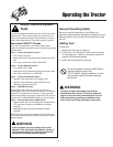
Operating the Tractor
Mower Deck Removal & Installation
Simplicity, Massey Ferguson or AGCO
Models
Removing the Mower Deck
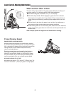
1. Park tractor on a hard, level surface such as a
concrete floor. Turn off PTO switch and engine,
remove the key and apply parking brake.
2. Place mower in the lowest cutting position using the
mower height adjuster.
3. Place the attachment lift in the lowest position.
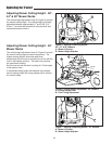
4. Disconnect the mower lift arm (A, Figure 10) from the
tractor lift arm (B). Re-install washer (C) and safety
clip (D).
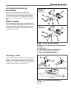
5. Remove belt from PTO pulley (B, Figure 11).
6. Turn wheels straight ahead. Pull back on spring-
loaded lever (B, Figure 12) and lift mower hitch off of
the tractor brackets.
7. Turn wheels fully left, and slide mower deck out right
side of tractor.
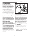
Installing the Mower Deck
1. Park tractor, shut off PTO and engine, remove the
key and apply parking brake. Turn the wheels fully to
the left.
2. Place mower height adjuster (B, Figures 5-7) in the
lowest cutting position. Place the mower lift lever in
the lowest position, also. Slide mower deck under
right side of tractor so that mower hitch is aligned
with the front tractor hitch.
3. See Figure 12. Turn wheels straight. Pull back on
the spring-loaded lever (B) while lifting up on the
mower hitch. Install mower hitch onto tractor hitch
brackets (A). When properly installed, the spring-
loaded lever should seat fully underneath the
brackets.
WARNING
Engage parking brake, disengage PTO, stop
engine and remove key before attempting to
install or remove the mower.
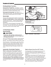
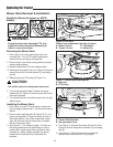
Figure 10. Lift Arms
(Viewed from underneath right side of tractor)
A. Mower Lift Arm C. Flat Washer
B. Tractor Lift Arm D. Safety Clip
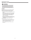
Figure 12. Mower Hitch
A. Tractor Hitch Brackets
B. Spring-Loaded Lever
A
B
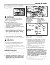
Figure 11. Removing & Installing Belt
A. Idler Arm
B. PTO Pulley
B
A
C
D
B
A
CAUTION
The muffler and surrounding areas may be hot.
4. See Figure 10. Connect the mower lift arm (A) to the
tractor lift arm (B) using the flat washer (C) and safety
clip (D).
5. See Figure 11. Move idler arm (A) to relieve belt
tension. Install belt onto the PTO pulley (B).