


5
SECTION 1 – ASSEMBLY INSTRUCTIONS
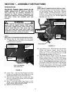
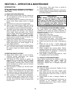
FIGURE 1.3
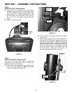
D. Align slotted hole in left Bumper Support with hole
in Bumper Bracket and insert (1) 5/16-18 x 1-3/4”
Flange Lock bolt. Tighten (4) Bumper bolts
securely. Place 5/16-18 Flange Lock hex nut on left
Bumper Support bolt and tighten securely. Tighten
right Bumper Support bolt securely. See Figure 1.3.
STEP 3
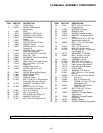
HITCH PLATE AND BAFFLE
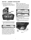
A. Attach triangular shaped Hitch Plate to bottom of
Front Cover Assembly. Orientation of the holes in
the Hitch Plate is important, observe picture
carefully before assembling. Align holes in Hitch
Plate and Front Cover Frame. Insert (2) 5/16-18 x
5/8” Flange Lock hex bolts and secure with (2)
5/16-18 Flange Lock hex nuts. Do not tighten at
this time. See Figure 1.4.
FIGURE 1.4
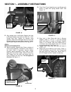
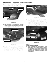
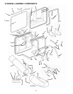
B. Place Front Cover Assembly over rear Bumper and
secure in place with spring loaded Latch. See
Figure 1.5.
FIGURE 1.5
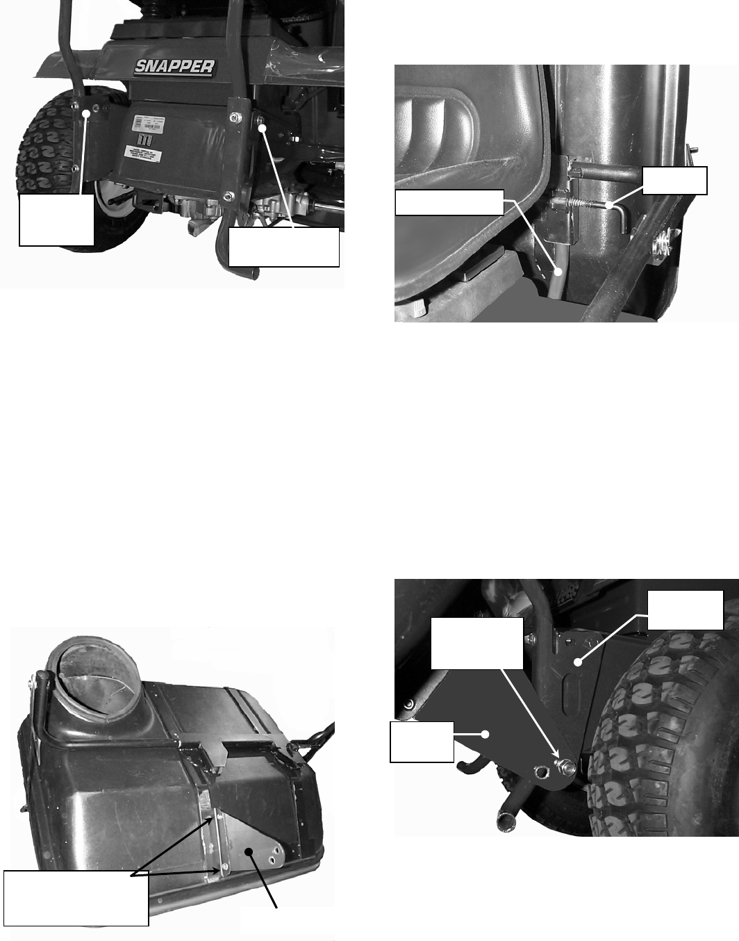
C. Align hole in Hitch Plate with hole in Bumper
Support. Insert (1) 1/2-13 x 1” hex bolt through
holes with head on inside of Bumper Support.
Place (1) 1/2” Internal Tooth Lock washer and (1)
1/2-13 hex nut on bolt (washer and nut on outside)
and tighten securely. See Figure 1.6.
D. Tighten Hitch Plate bolts that were left loose in
STEP 3, “A”.
E. Attach left end of baffle to Front Cover. Place (1)
3/16” Flat Washer over #10-24 x 3/4” Flange Lock
Bolt and insert from inside cover. Secure with (1)
#10-24 Flange Lock Nut. Tighten nut securely.
FIGURE 1.6
LEFT
BUMPER
SUPPORT
RIGHT BUMPER
SUPPORT BOLT
HITCH PLATE
5/16-18X5/8” FLANGE
LOCK BOLT & 5/16-18
FLANGE LOCK NUTS
LATCH
REAR BUMPER
BUMPER
SUPPORT
HITCH
PLATE
1/2-13 NUT &
1/2” LOCK
WASHER